Infiniti I35 (A33). Manual — part 133

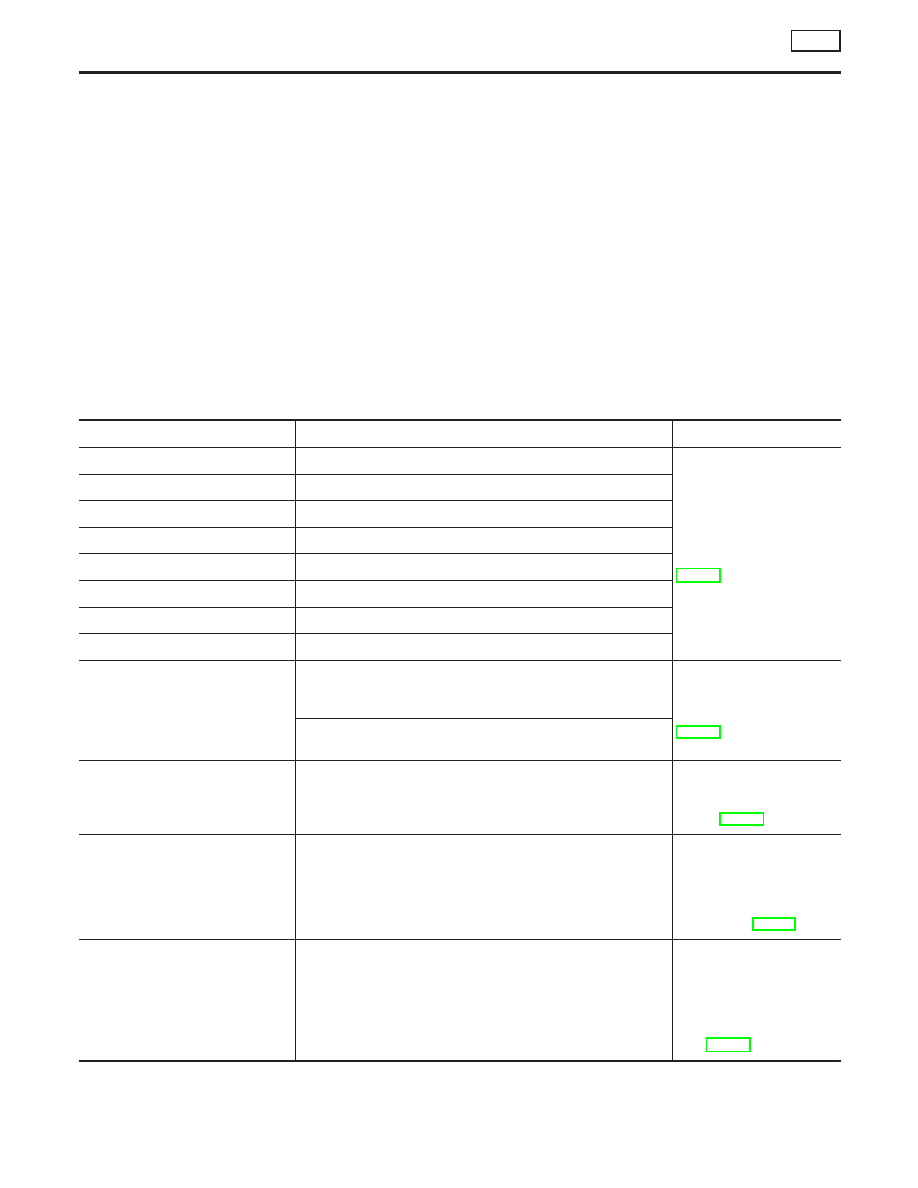
Data monitor item
Contents
Data monitor
(Reference) Check items
for malfunction
Condition
Reference value
in normal opera-
tion
PARK BRAKE SW
Parking brake status
Parking brake activated
ON
Parking brake switch cir-
cuit
Parking brake not activated
OFF
OFF SW
VDC OFF SW
ON/OFF condition
VDC OFF switch ON
(When VDC OFF indicator
lamp is ON.)
ON
VDC OFF switch circuit
VDC OFF switch OFF
(When VDC OFF indicator
lamp is OFF.)
OFF
ABS WARN LAMP
ABS warning lamp sta-
tus (Note 2)
When ABS warning lamp is
ON.
ON
ABS warning lamp circuit
When ABS warning lamp is
OFF.
OFF
OFF LAMP
VDC OFF indicator
lamp status (Note 3)
When VDC OFF indicator lamp
is ON.
ON
VDC OFF indicator lamp
circuit
When VDC OFF indicator lamp
is OFF.
OFF
SLIP LAMP
SLIP indicator lamp
status (Note 4)
When SLIP indicator lamp is
ON
ON
SLIP indicator lamp circuit
When SLIP indicator lamp is
OFF
OFF
FR LH IN SOL
FR LH OUT SOL
FR RH IN SOL
FR RH OUT SOL
RR LH IN SOL
RR LH OUT SOL
RR RH IN SOL
RR RH OUT SOL
Solenoid valve opera-
tion
Actuator (solenoid valve) is
active (“Active Test” with CON-
SULT-II) or actuator relay is
inactive (in fail-safe mode).
ON
Solenoid valve and circuit
When the actuator (solenoid
valve) is not active and actua-
tor relay is active (ignition
switch ON).
OFF
USV [FR-RL]
UISV [FL-RR]
HSV [FR-RL]
HSV [FL-RR]
VDC switch-over sole-
noid valve status
When the actuator (switch-over
solenoid valve) is active
(“Active test” with CONSULT-II)
or the actuator relay is inactive
(when fail-safe mode).
ON
Switch-over solenoid valve
and circuit
When the actuator (switch-over
solenoid valve) is inactive or
the actuator relay is active
(ignition switch ON).
OFF
V/R OUTPUT
Actuator relay acti-
vated
ON/OFF
When the actuator relay is
active (the engine is running).
ON
Actuator relay and circuit
When the actuator relay is not
active (before the engine get
started and in the fail-safe
mode).
OFF
M/R OUTPUT
Actuator motor and
motor relay status (ON/
OFF)
When the actuator motor and
motor relay are active (“Active
test” with CONSULT-II).
ON
Actuator motor, motor
relay, and circuit
When the actuator motor and
motor relay are inactive.
OFF
GI
MA
EM
LC
EC
FE
AT
AX
SU
ST
RS
BT
HA
SC
EL
IDX
TROUBLE DIAGNOSIS — INTRODUCTION
VDC
Control Unit Input/Output Signal Standard (Cont’d)
BR-117

Data monitor item
Contents
Data monitor
(Reference) Check items
for malfunction
Condition
Reference value
in normal opera-
tion
FLUID LEV SW
Brake fluid level warn-
ing switch status.
When brake fluid level warning
switch is ON.
ON
Brake fluid level warning
switch, brake warning
lamp and circuit.
When brake fluid lever warning
switch is OFF.
OFF
EBD FAIL SIG
ABS FAIL SIG
TCS FAIL SIG
VDC FAIL SIG
System fail signal sta-
tus
Malfunctions condition
(When system failed)
OFF
EBD system
ABS system
TCS system
VDC system
(Note 1): Check the pressure of the tire in normal condition.
(Note 2): ON/OFF timing of the ABS warning lamp
ON: For approximately 0.5 seconds after the ignition switch is turned ON, or when a malfunction is detected.
OFF: Approximately 0.5 seconds after the ignition switch is turned ON (when the system is in normal operation).
(Note 3): ON/OFF timing of the VDC OFF indicator lamp
ON: For approximately 0.5 seconds after the ignition switch is turned ON, or when a malfunction is detected VDC OFF switch is ON.
OFF: Approximately 0.5 seconds after the ignition switch is turned ON (when the system is in normal operation) or when VDC OFF
switch is OFF.
(Note 4): SLIP indicator lamp ON/OFF timing
ON: For approximately 0.5 seconds after the ignition switch is turned ON, or when a malfunction is detected.
OFF: Approximately 0.5 seconds after the ignition switch is turned ON (when the system is in normal operation) and VDC/TCS func-
tion is not activated.
Flashing: VDC/TCS function is active during driving.
CONSULT-II Functions
NHBR0264
CONSULT-II MAIN FUNCTION
NHBR0264S01
In a diagnosis function (main function), there are “WORK
SUPPORT”, “SELF-DIAGNOSTIC RESULTS”, “DATA MONITOR”,
“CAN DIAG SUPPORT MNTR”, “ACTIVE TEST”, “FUNCTION
TEST”, “ECU PART NUMBER”.
Diagnostic test
mode
Function
Reference
WORK SUP-
PORT
This mode enables a technician to adjust some devices faster and more
accurately by following the indications on CONSULT-II.
Refer to BR-93.
SELF-DIAG-
NOSTIC
RESULTS
Self-diagnostic results can be read and erased quickly.
Refer to BR-119.
DATA MONITOR
Input/Output data in the ABS actuator and electric unit (control unit) can
be read.
Refer to BR-123.
CAN DIAG SUP-
PORT MNTR
The results of transmit/receive diagnosis of communication can be read.
—
ACTIVE TEST
Diagnostic Test Mode in which CONSULT-II drives some actuators apart
from the ABS actuator and electric unit (control unit) and also shifts some
parameters in a specified range.
Refer to BR-126.
TROUBLE DIAGNOSIS — INTRODUCTION
VDC
Control Unit Input/Output Signal Standard (Cont’d)
BR-118

Diagnostic test
mode
Function
Reference
FUNCTION
TEST
Conducted by CONSULT-II instead of a technician to determine whether
each system is “OK” or “NG”.
—
ECU PART
NUMBER
ABS actuator and electric unit (control unit) part number can be read.
—
SELF-DIAGNOSIS
NHBR0264S02
Description
If a malfunction is detected in the system, the ABS warning lamp,
VDC OFF indicator lamp, and SLIP indicator lamp on the meter
turn on. In this case, perform the self-diagnosis as follows:
Procedure
1.
Perform a Basic Inspection, BR-131, using information from
the customer.
SBR535E
2.
After the ignition switch is turned OFF, connect the CON-
SULT-II connector to the vehicle-side data link connector. (The
data link connector is on the lower instrument cover).
3.
Start the engine and drive at Approx. 30 km/h (19 MPH) or
more for approx. 1 minute.
SFIA2436E
4.
After stopping the vehicle, with the engine still idling, touch
“START”, “ABS”, “SELF-DIAG RESULTS” on the CONSULT-II
screen in this order.
CAUTION:
Just after starting the engine, or turning the ignition switch
ON, “ABS” may not be displayed on the system selection
screen even if “START” is touched. In this case, start the self-
diagnosis again from step 2. If it cannot be shown after sev-
eral attempts, the VDC/TCS/ABS control unit may malfunction.
Repair or replace the control unit.
5.
The self-diagnosis result is displayed. (If necessary, touch
“PRINT” to print the self-diagnosis result.)
I
When “NO FAILURE” is shown, check the ABS warning lamp,
VDC OFF indicator lamp, SLIP indicator lamp. Refer to For
Correct and Quick Diagnosis, BR-129.
I
CONSULT-II self-diagnosis results are displayed without
regard to occurrence timing. In some case, the later ones (tim-
ing value is small) appear on the next screen.
6.
Go to appropriate “Inspection” chart according to “Self-Diag-
nostic Items to Result Mode” and repair or replace as neces-
sary.
GI
MA
EM
LC
EC
FE
AT
AX
SU
ST
RS
BT
HA
SC
EL
IDX
TROUBLE DIAGNOSIS — INTRODUCTION
VDC
CONSULT-II Functions (Cont’d)
BR-119
7.
Start the engine and drive at Approx. 30 km/h (19 MPH) or
more for Approx. 1 minute.
CAUTION:
Check again to make sure that there is NO MALFUNCTION on
other parts.
8.
Turn the ignition switch OFF to prepare for erasing the
memory.
9.
Start the engine and touch “START”, “ABS”, “SELF-DIAG
RESULTS” and “ERASE” on CONSULT-II screen in this order
to ease the memory.
CAUTION:
If the memory cannot be erased, go to step 6.
10. Drive the vehicle at Approx. 30 km/h (19 MPH) or more and
check that the ABS warning lamp, VDC OFF indicator lamp,
and SLIP indicator lamp stay off.
CAUTION:
VDC OFF switch is not cancelled.
Self-diagnostic items to result mode
Self-Diagnostic item
Malfunction detecting condition
Check route
FR LH SENSOR – 1
Circuit of front LH wheel sensor is open.
Wheel sensor and circuit.
Refer to Inspection 1
Wheel Sensor and Circuit,
BR-133.
RR RH SENSOR – 1
Circuit of rear RH wheel sensor is open.
FR RH SENSOR – 1
Circuit of front RH wheel sensor is open.
RR LH SENSOR – 1
Circuit of rear LH wheel sensor is open.
FR LH SENSOR – 2
Front LH wheel sensor is shorted or input signal is abnormal.
RR RH SENSOR – 2
Rear RH wheel sensor is shorted or input signal is abnormal.
FR RH SENSOR – 2
Front RH wheel sensor is shorted or input signal is abnormal.
RR LH SENSOR – 2
Rear LH wheel sensor is shorted or input signal is abnormal.
MAIN RELAY
During the actuator relay operation with OFF, when the actuator
relay turns ON. Or when the control line for the relay is shorted
to the ground.
Actuator relay and circuit.
Refer to Inspection 9
Actuator Relay and Circuit,
BR-148.
During the actuator relay operation with ON, when the actuator
relay turns OFF. Or when the control line for the relay is open.
STOP LAMP SW
Stop lamp switch circuit is open.
Stop lamp switch and cir-
cuit. Refer to Inspection 10
Stop Lamp Switch and
Circuit, BR-150.
PRESS SEN CIRCUIT
Pressure sensor signal line is open or shorted, or pressure sen-
sor is abnormal.
Pressure sensor and cir-
cuit. Refer to Inspection 4
Pressure Sensor and the
Circuit between Pressure
Sensor and VDC/TCS/ABS
Control Unit, BR-137.
ST ANGLE SEN CIRCUIT
Neutral position of the steering angle sensor is dislocated, or
the steering angle sensor is abnormal.
Steering angle sensor and
circuit. Refer to Inspection
5 Steering Angle Sensor
and the Circuit between
Steering Angle Sensor and
VDC/TCS/ABS Control
Unit, BR-139.
TROUBLE DIAGNOSIS — INTRODUCTION
VDC
CONSULT-II Functions (Cont’d)
BR-120
Нет комментариевНе стесняйтесь поделиться с нами вашим ценным мнением.
Текст