Infiniti I35 (A33). Manual — part 585

STARTING & CHARGING SYSTEM
CONTENTS
PRECAUTIONS . . . . . . . . . . . . . . . ...2
Precautions for Supplemental Restraint System
(SRS)
. . . . . . . . . . . . . ..2
Wiring Diagrams and Trouble Diagnosis. . . . . .2
PREPARATION . . . . . . . . . . . . . . . ...3
Special Service Tool . . . . . . . . . . . . . 3
BATTERY. . . . . . . . . . . . . . . . . . .4
How to Handle Battery . . . . . . . . . . . . 4
METHODS OF PREVENTING OVER-DISCHARGE
. ..4
. . . . . . . 4
. . . . . . . . . ..5
. . . . . . . . . . 6
Trouble Diagnoses with Battery/Starting/Charging
System Tester . . . . . . . . . . . . . . . ..7
STARTING SYSTEM . . . . . . . . . . . . . .10
System Description. . . . . . . . . . . . . 10
Wiring Diagram - START -. . . . . . . . . . . 11
Trouble Diagnoses with Battery/Starting/Charging
System Tester . . . . . . . . . . . . . . . 12
. . . . . . 13
. . . . . . . . . . . . . . ..14
. . . . . . . . ..15
. . . . . . . . ..17
MINIMUM SPECIFICATION OF CRANKING
VOLTAGE REFERENCING COOLANT
TEMPERATURE
. . . . . . . . . . . . . ..18
Construction. . . . . . . . . . . . . . . ...18
Removal and Installation . . . . . . . . . . ...18
. . . . . . . . . . . . . . . ...18
. . . . . . . . . . . . . . 19
Pinion/Clutch Check . . . . . . . . . . . . ..19
CHARGING SYSTEM . . . . . . . . . . . . . 20
System Description. . . . . . . . . . . . . 20
Wiring Diagram - CHARGE -. . . . . . . . . .21
Trouble Diagnoses with Battery/Starting/Charging
System Tester . . . . . . . . . . . . . . . 22
. . . . . . 24
. . . . . . . . . . . . . . ..25
. . . . . . . . ..26
. . . . . . . . ..27
. . . . . . . . ..28
. . . . . . . . . 28
Construction. . . . . . . . . . . . . . . ...29
Removal and Installation . . . . . . . . . . ...29
. . . . . . . . . . . . . . . ...29
. . . . . . . . . . . . . . 29
SERVICE DATA AND SPECIFICATIONS (SDS) . . .30
Battery. . . . . . . . . . . . . . . . . . 30
Starter . . . . . . . . . . . . . . . . . . 30
Alternator . . . . . . . . . . . . . . . . ...30
GI
MA
EM
LC
EC
FE
AT
AX
SU
BR
ST
RS
BT
HA
EL
IDX
Precautions for Supplemental Restraint System
(SRS) “AIR BAG” and “SEAT BELT
PRE-TENSIONER”
NHSC0001
The Supplemental Restraint System such as “AIR BAG” and “SEAT BELT PRE-TENSIONER”, used along with
a front seat belt, helps to reduce the risk or severity of injury to the driver and front passenger for certain types
of collision. This system includes seat belt switch inputs and dual stage front air bag modules. The SRS sys-
tem uses the seat belt switches to determine the front air bag deployment, and may only deploy one front air
bag, depending on the severity of a collision and whether the front occupants are belted or unbelted.
Information that is necessary to service the system safely is included in the RS section of this Service Manual.
WARNING:
I
To avoid rendering the SRS inoperative, which could increase the risk of personal injury or death
in the event of a collision which would result in air bag inflation, all maintenance must be performed
by an authorized NISSAN/INFINITI dealer.
I
Improper maintenance, including incorrect removal and installation of the SRS, can lead to per-
sonal injury caused by unintentional activation of the system. For removal of Spiral Cable and Air
Bag Module, see the RS section.
I
Do not use electrical test equipment on any circuit related to the SRS unless instructed to in this
Service Manual. SRS wiring harnesses can be identified by yellow and/or orange harnesses or
harness connectors.
Wiring Diagrams and Trouble Diagnosis
NHSC0002
When you read wiring diagrams, refer to the following:
I
GI-11, “HOW TO READ WIRING DIAGRAMS”
I
EL-11, “POWER SUPPLY ROUTING” for power distribution circuit
When you perform trouble diagnosis, refer to the following:
I
GI-36, “HOW TO FOLLOW TEST GROUPS IN TROUBLE DIAGNOSES”
I
GI-25, “HOW TO PERFORM EFFICIENT DIAGNOSES FOR AN ELECTRICAL INCIDENT”
PRECAUTIONS
Precautions for Supplemental Restraint System (SRS) “AIR BAG” and “SEAT BELT PRE-TENSIONER”
SC-2
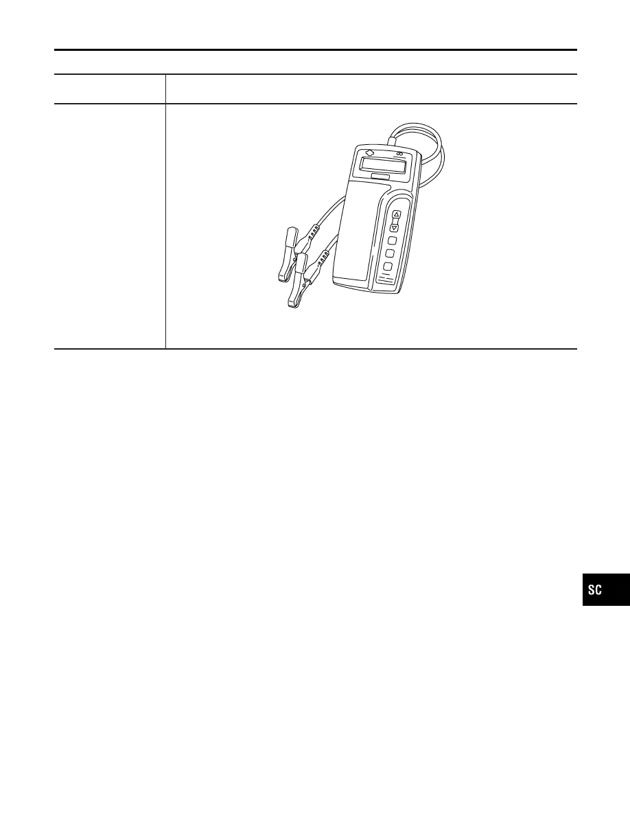
Special Service Tool
NHSC0017
Tool number
Tool name
Description
J-44373 Model 620
Battery/Starting/Charging
system tester
SEL403X
GI
MA
EM
LC
EC
FE
AT
AX
SU
BR
ST
RS
BT
HA
EL
IDX
PREPARATION
Special Service Tool
SC-3
How to Handle Battery
NHSC0003
CAUTION:
I
If it becomes necessary to start the engine with a booster
battery and jumper cables, use a 12-volt booster battery.
I
After connecting battery cables, ensure that they are
tightly clamped to battery terminals for good contact.
I
Never add distilled water through the hole used to check
specific gravity.
MEL040F
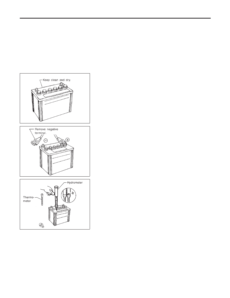
METHODS OF PREVENTING OVER-DISCHARGE
NHSC0003S01
The following precautions must be taken to prevent over-discharg-
ing a battery.
I
The battery surface (particularly its top) should always be kept
clean and dry.
I
The terminal connections should be clean and tight.
I
At every routine maintenance, check the electrolyte level.
This also applies to batteries designated as “low maintenance”
and “maintenance-free”.
MEL041F
I
When the vehicle is not going to be used over a long period of
time, disconnect the negative battery terminal. (If the vehicle
has an extended storage switch, turn it off.)
MEL042F
I
Check the charge condition of the battery.
Periodically check the specific gravity of the electrolyte. Keep
a close check on charge condition to prevent over-discharge.
CHECKING ELECTROLYTE LEVEL
NHSC0003S02
WARNING:
Do not allow battery fluid to come in contact with skin, eyes,
fabrics, or painted surfaces. After touching a battery, do not
touch or rub your eyes until you have thoroughly washed your
hands. If acid contacts eyes, skin or clothing, immediately
flush with water for 15 minutes and seek medical attention.
BATTERY
How to Handle Battery
SC-4
Нет комментариевНе стесняйтесь поделиться с нами вашим ценным мнением.
Текст