Infiniti I35 (A33). Manual — part 80
SAT705J
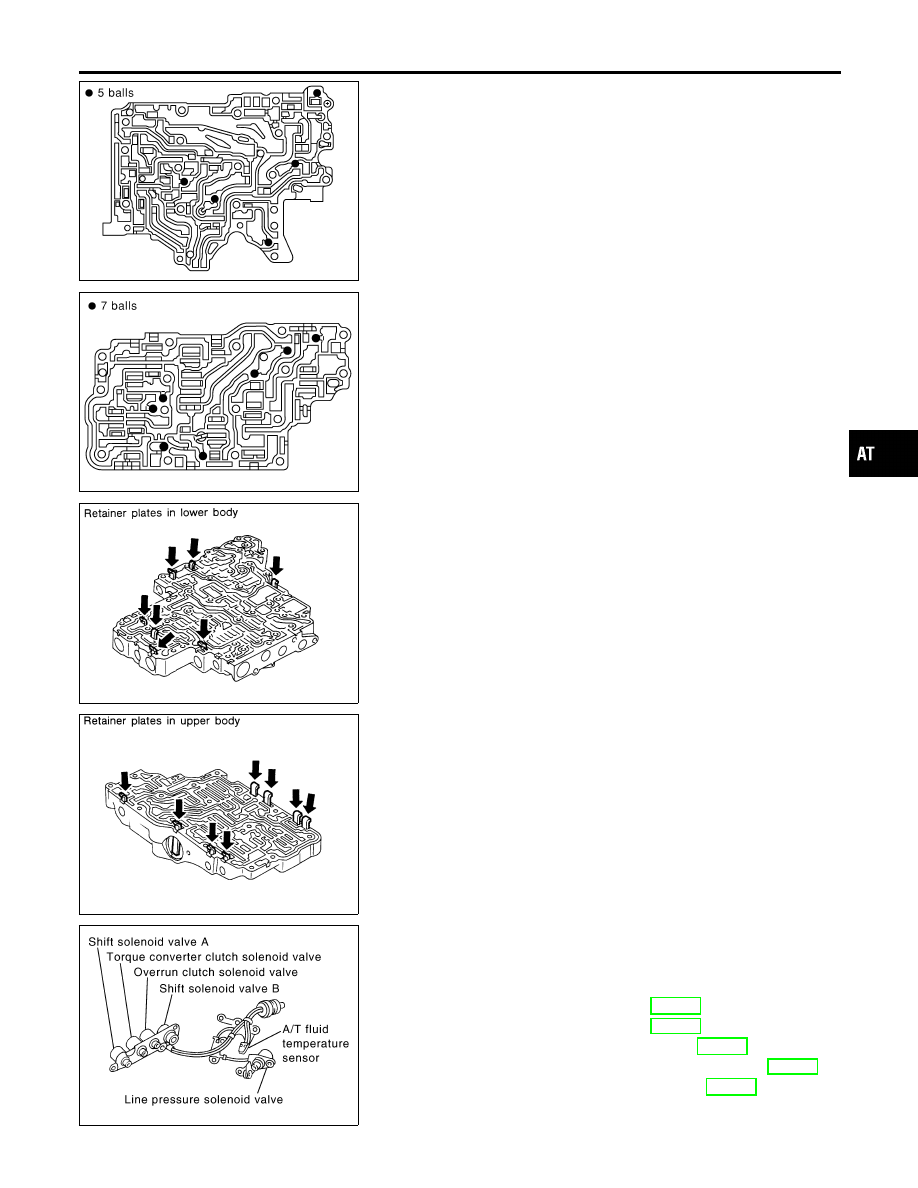
10. Check to see that steel balls are properly positioned in inter
body and then remove them.
I
Be careful not to lose steel balls.
SAT771J
11. Check to see that steel balls are properly positioned in upper
body and then remove them.
I
Be careful not to lose steel balls.
SAT550G
INSPECTION
NHAT0135
Lower and Upper Bodies
NHAT0135S01
I
Check to see that retainer plates are properly positioned in
lower body.
SAT551G
I
Check to see that retainer plates are properly positioned in
upper body.
I
Be careful not to lose these parts.
Oil Strainer
NHAT0135S02
I
Check wire netting of oil strainer for damage.
SAT820K
Shift Solenoid Valves “A” and “B”, Line Pressure
Solenoid Valve, Torque Converter Clutch Solenoid
Valve and Overrun Clutch Solenoid Valve
NHAT0135S03
I
Measure resistance.
I
For shift solenoid valve A, refer to AT-178.
I
For shift solenoid valve B, refer to AT-183.
I
For line pressure solenoid valve, refer to AT-172.
I
For torque converter clutch solenoid valve, refer to AT-157.
I
For overrun clutch solenoid valve, refer to AT-194.
GI
MA
EM
LC
EC
FE
AX
SU
BR
ST
RS
BT
HA
SC
EL
IDX
REPAIR FOR COMPONENT PARTS
Control Valve Assembly (Cont’d)
AT-317
SAT138D
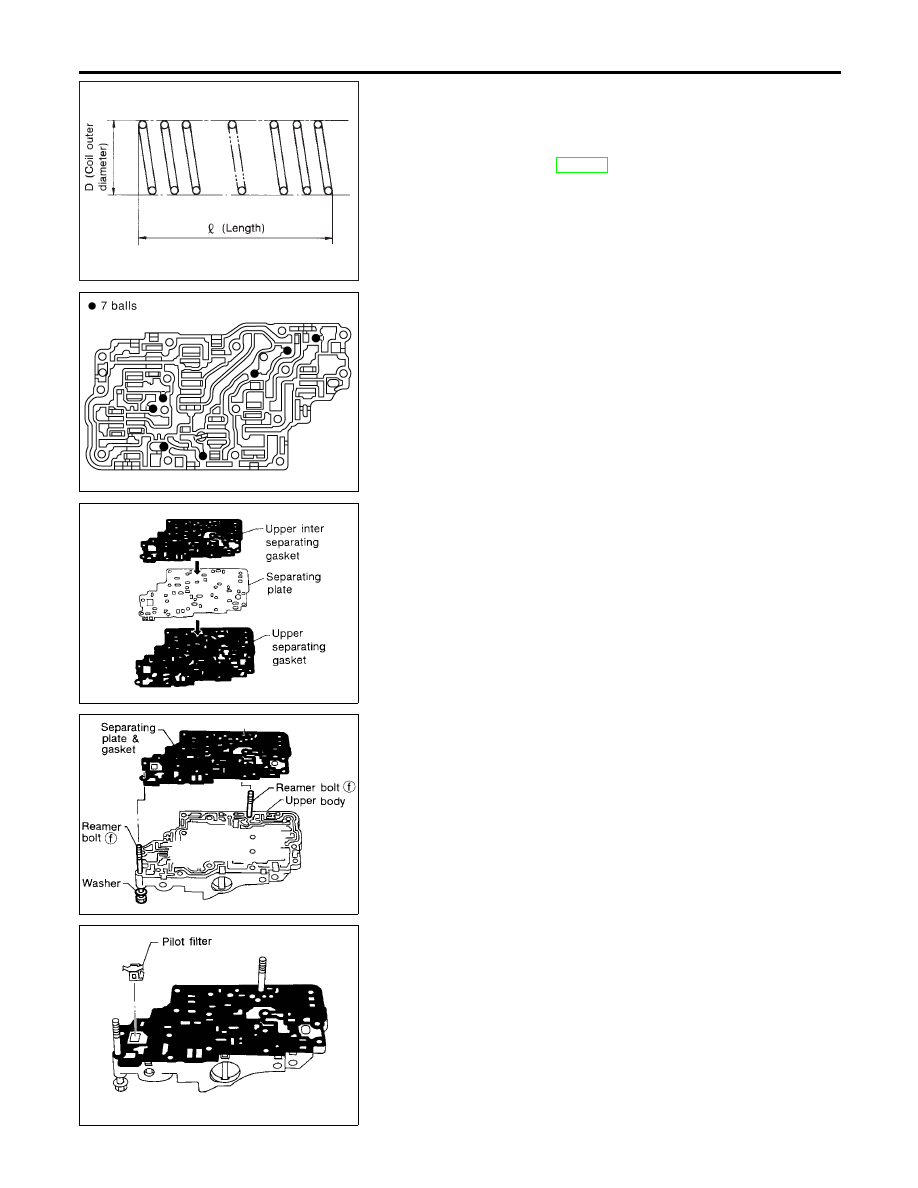
Oil Cooler Relief Valve Spring
NHAT0135S04
I
Check springs for damage or deformation.
I
Measure free length and outer diameter.
Inspection standard:
Refer to SDS, AT-382.
SAT771J
ASSEMBLY
NHAT0136
1.
Install upper, inter and lower body.
a.
Place oil circuit of upper body face up. Install steel balls in their
proper positions.
SAT072F
b.
Install upper separating gasket, upper inter separating gasket
and upper separating plate in order shown in illustration.
SAT073FA
c.
Install reamer bolts f from bottom of upper body. Using reamer
bolts as guides, install separating plate and gaskets as a set.
SAT074F
d.
Install pilot filter.
REPAIR FOR COMPONENT PARTS
Control Valve Assembly (Cont’d)
AT-318
SAT705J
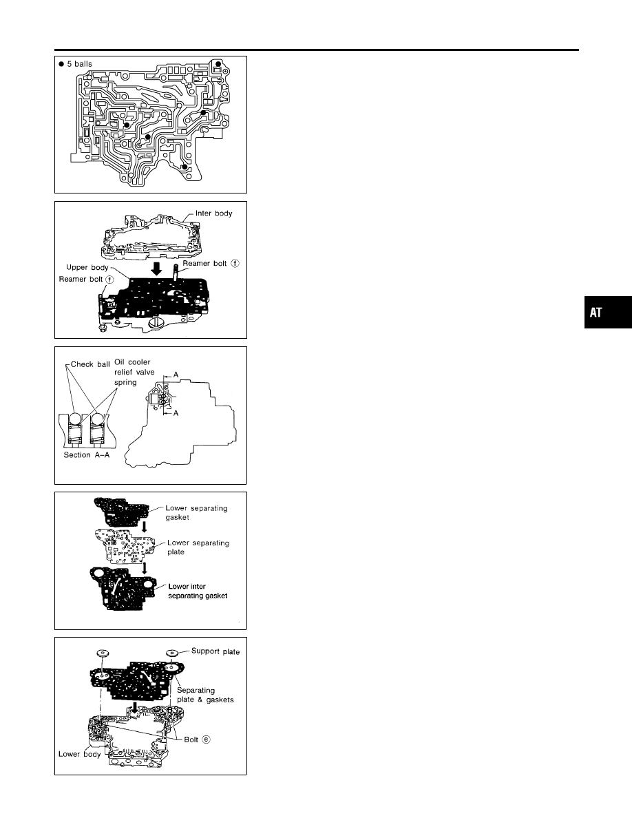
e.
Place lower body as shown in illustration (side of inter body
face up). Install steel balls in their proper positions.
SAT076FA
f.
Install inter body on upper body using reamer bolts f as guides.
I
Be careful not to dislocate or drop steel balls.
SAT110DA
g.
Install check balls and oil cooler relief valve springs in their
proper positions in lower body.
BAT002
h.
Install lower separating gasket, lower inter separating gasket
and lower separating plate in order shown in illustration.
SAT078FA
i.
Install bolts e from bottom of lower body. Using bolts e as
guides, install separating plate and gaskets as a set.
j.
Temporarily install support plates on lower body.
GI
MA
EM
LC
EC
FE
AX
SU
BR
ST
RS
BT
HA
SC
EL
IDX
REPAIR FOR COMPONENT PARTS
Control Valve Assembly (Cont’d)
AT-319
SAT126DA
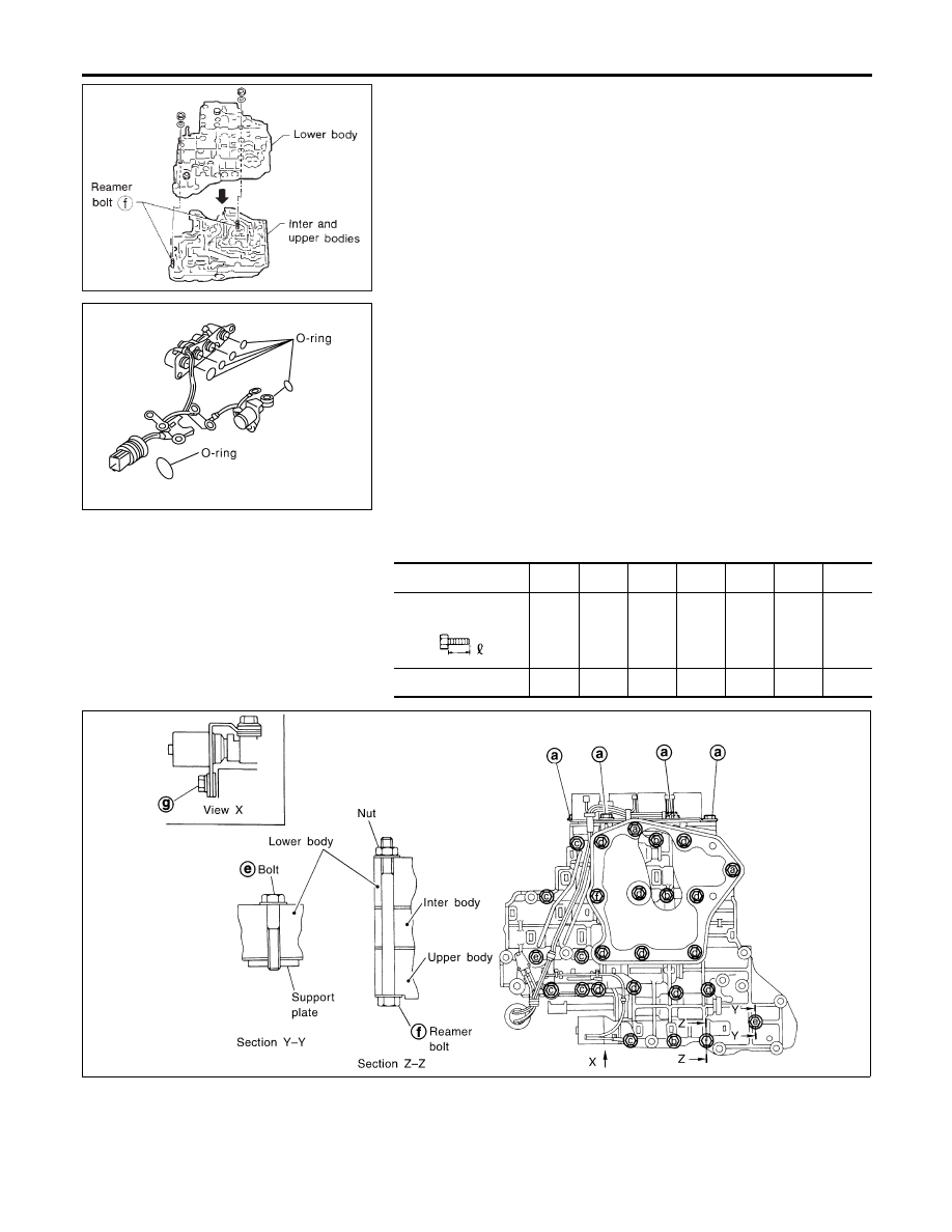
k.
Install lower body on inter body using reamer bolts f as guides
and tighten reamer bolts f slightly.
SCIA0804E
2.
Install O-rings to solenoid valves and terminal body.
I
Apply ATF to O-rings.
3.
Install and tighten bolts.
Bolt length, number and location:
Bolt symbol
a
b
c
d
e
f
g
Bolt length “
”
mm
(in)
13.5
(0.531)
58.0
(2.283)
40.0
(1.575)
66.0
(2.598)
33.0
(1.299)
78.0
(3.071)
18.0
(0.709)
Number of bolts
6
3
6
11
2
2
1
SAT704J
REPAIR FOR COMPONENT PARTS
Control Valve Assembly (Cont’d)
AT-320
Нет комментариевНе стесняйтесь поделиться с нами вашим ценным мнением.
Текст