Infiniti I35 (A33). Manual — part 79
SAT051F
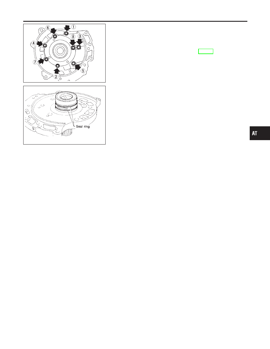
4.
Install oil pump cover on oil pump housing.
a.
Wrap masking tape around splines of oil pump cover assem-
bly to protect seal. Position oil pump cover assembly on oil
pump housing assembly, then remove masking tape.
b.
Tighten bolts in a crisscross pattern. Tighten oil pump cover
bolts to the specified torque. Refer to AT-310.
SAT699H
5.
Install new seal rings carefully after packing ring groove with
petroleum jelly.
I
Do not spread gap of seal ring excessively while install-
ing. The ring may be deformed.
GI
MA
EM
LC
EC
FE
AX
SU
BR
ST
RS
BT
HA
SC
EL
IDX
REPAIR FOR COMPONENT PARTS
Oil Pump (Cont’d)
AT-313
Control Valve Assembly
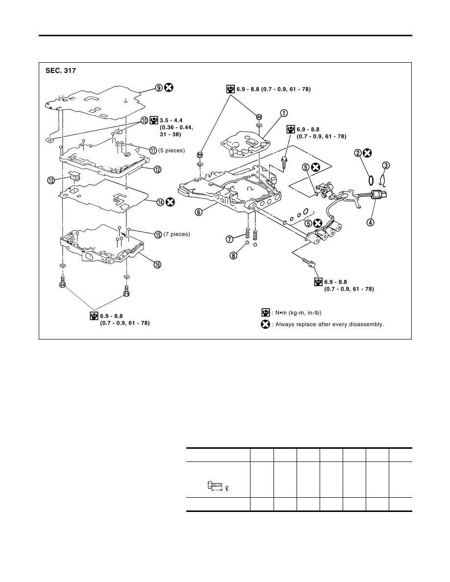
COMPONENTS
=NHAT0133
SAT838K
1.
Oil strainer
2.
O-ring
3.
Snap ring
4.
Terminal body
5.
O-rings
6.
Control valve lower body
7.
Oil cooler relief valve spring
8.
Check ball
9.
Separating plate
10. Support plate
11. Steel ball
12. Control valve inter body
13. Pilot filter
14. Separating plate
15. Steel ball
16. Control valve upper body
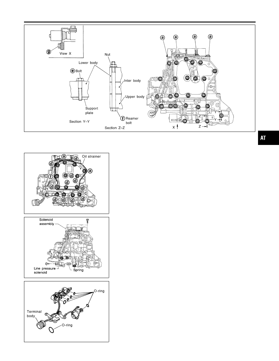
DISASSEMBLY
NHAT0134
Disassemble upper, inter and lower bodies.
Bolt length, number and location:
Bolt symbol
a
b
c
d
e
f
g
Bolt length “
”
mm
(in)
13.5
(0.531)
58.0
(2.283)
40.0
(1.575)
66.0
(2.598)
33.0
(1.299)
78.0
(3.071)
18.0
(0.709)
Number of bolts
6
3
6
11
2
2
1
f: Reamer bolt and nut.
REPAIR FOR COMPONENT PARTS
Control Valve Assembly
AT-314
SAT704J
SAT839K
1.
Remove bolts a, d and nut f and remove oil strainer from con-
trol valve assembly.
SAT062F
2.
Remove solenoid valve assembly and line pressure solenoid
valve from control valve assembly.
SAT840K
3.
Remove O-rings from solenoid valves and terminal body.
GI
MA
EM
LC
EC
FE
AX
SU
BR
ST
RS
BT
HA
SC
EL
IDX
REPAIR FOR COMPONENT PARTS
Control Valve Assembly (Cont’d)
AT-315
SAT064FA
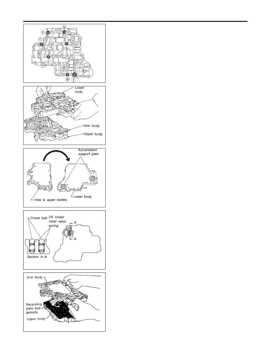
4.
Place upper body facedown, and remove bolts b, c and nut f.
SAT432D
5.
Remove inter body from lower body.
SAT109D
6.
Turn over lower body, and remove accumulator support plate.
SAT110DA
7.
Remove bolts e, separating plate and separating gasket from
lower body.
8.
Remove check balls and oil cooler relief valve springs from
lower body.
I
Be careful not to lose check balls and oil cooler relief
valve springs.
SAT065F
9.
Remove inter body from upper body.
REPAIR FOR COMPONENT PARTS
Control Valve Assembly (Cont’d)
AT-316
Нет комментариевНе стесняйтесь поделиться с нами вашим ценным мнением.
Текст