Infiniti I35 (A33). Manual — part 326
Wiring Diagram
NHEC1282
MEC370E
GI
MA
EM
LC
FE
AT
AX
SU
BR
ST
RS
BT
HA
SC
EL
IDX
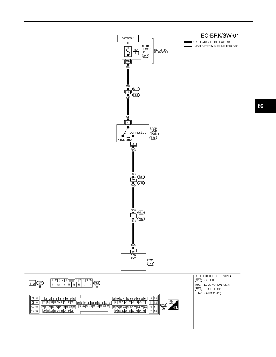
DTC P1805 BRAKE SWITCH
Wiring Diagram
EC-645

Specification data are reference values and are measured between each terminal and body ground.
CAUTION:
Do not use ECM ground terminals when measuring input/output voltage. Doing so may result in dam-
age to the ECM’s transistor. Use a ground other than ECM terminals, such as the ground.
TER-
MINAL
NO.
WIRE
COLOR
ITEM
CONDITION
DATA (DC Voltage)
55
R/G
Stop lamp switch
[Engine is running]
I
Brake pedal released
Approximately 0V
[Engine is running]
I
Brake pedal depressed
BATTERY VOLTAGE
(11 - 14V)
Diagnostic Procedure
NHEC1283
1
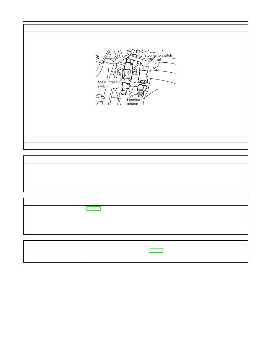
CHECK STOP LAMP SWITCH CIRCUIT
1. Turn ignition switch OFF.
2. Check the stop lamp when depressing and releasing the brake pedal.
MTBL1138
OK or NG
OK
©
GO TO 4.
NG
©
GO TO 2.
DTC P1805 BRAKE SWITCH
Wiring Diagram (Cont’d)
EC-646

2
CHECK STOP LAMP SWITCH POWER SUPPLY CIRCUIT
1. Disconnect stop lamp switch harness connector.
SEC053D
2. Check voltage between stop lamp switch terminal 1 and ground with CONSULT-II or tester.
SEC051D
Voltage: Battery voltage
OK or NG
OK
©
GO TO 4.
NG
©
GO TO 3.
3
DETECT MALFUNCTIONING PART
Check the following.
I
Harness connectors M15, E81
I
15A fuse
I
Fuse block (J/B) connector M17
I
Harness for open and short between stop lamp switch and battery
©
Repair open circuit or short to ground or short to power in harness or connectors.
GI
MA
EM
LC
FE
AT
AX
SU
BR
ST
RS
BT
HA
SC
EL
IDX
DTC P1805 BRAKE SWITCH
Diagnostic Procedure (Cont’d)
EC-647
4
CHECK STOP LAMP SWITCH INPUT SIGNAL CIRCUIT FOR OPEN AND SHORT
1. Turn ignition switch OFF.
2. Disconnect ECM harness connector.
3. Disconnect stop lamp switch harness connector.
SEC053D
4. Check harness continuity between ECM terminal 55 and stop lamp switch terminal 2.
Refer to Wiring Diagram.
Continuity should exist.
5. Also check harness for short to ground and short to power.
OK or NG
OK
©
GO TO 6.
NG
©
GO TO 5.
5
DETECT MALFUNCTIONING PART
Check the following.
I
Harness connectors E81, M15
I
Harness connectors M223, F53
I
Harness for open or short between ECM and stop lamp switch
©
Repair open circuit or short to ground or short to power in harness or connectors.
6
CHECK STOP LAMP SWITCH
Refer to “Component Inspection”, EC-649.
OK or NG
OK
©
GO TO 7.
NG
©
Replace stop lamp switch.
7
CHECK INTERMITTENT INCIDENT
Refer to “TROUBLE DIAGNOSIS FOR INTERMITTENT INCIDENT”, EC-152.
©
INSPECTION END
DTC P1805 BRAKE SWITCH
Diagnostic Procedure (Cont’d)
EC-648
Нет комментариевНе стесняйтесь поделиться с нами вашим ценным мнением.
Текст