Infiniti I35 (A33). Manual — part 502
ACCELERATOR CONTROL, FUEL &
EXHAUST SYSTEMS
CONTENTS
PREPARATION . . . . . . . . . . . . . . . ...2
Special Service Tool . . . . . . . . . . . . . 2
Commercial Service Tools . . . . . . . . . . ...2
ACCELERATOR CONTROL SYSTEM . . . . . . ...3
Removal and Installation . . . . . . . . . . . .3
. . . . . . . . . . . . . . . . .3
. . . . . . . . . . . . . . ..3
. . . . . . .3
FUEL SYSTEM . . . . . . . . . . . . . . . . 4
Removal and Installation . . . . . . . . . . . .4
Fuel Tank . . . . . . . . . . . . . . . . . .5
. . . . . . . . . . . . . . . . .5
. . . . . . . . . . . . . . ..5
Fuel Pump, Fuel Level Sensor Unit and Fuel
Filter . . . . . . . . . . . . . . . . . . . .6
. . . . . . . . . . . . . . . . .6
. . . . . . . . . . . . . . ..8
EXHAUST SYSTEM . . . . . . . . . . . . . . 9
Removal and Installation . . . . . . . . . . . .9
GI
MA
EM
LC
EC
AT
AX
SU
BR
ST
RS
BT
HA
SC
EL
IDX
Special Service Tool
NHFE0001
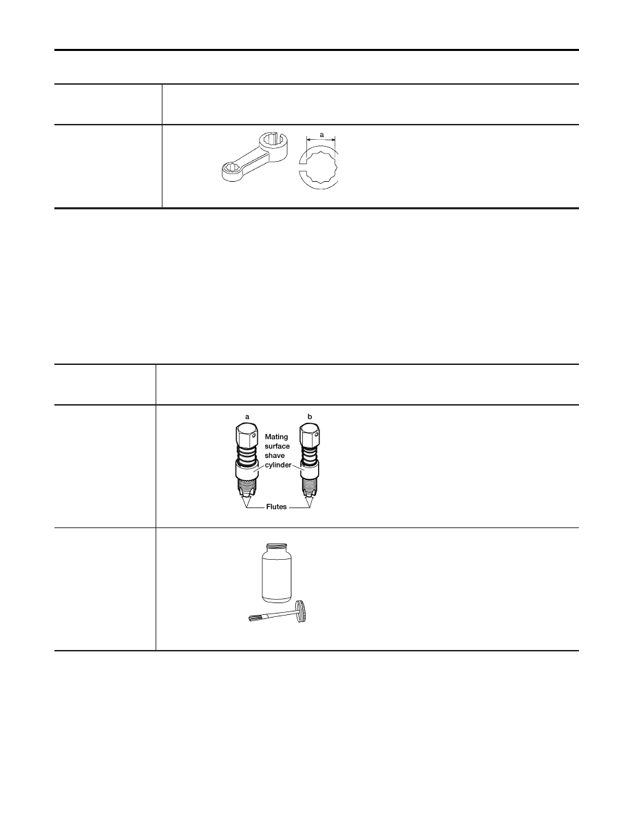
The actual shapes of Kent-Moore tools may differ from those of special service tools illustrated here.
Tool number
(Kent-Moore No.)
Tool name
Description
KV10114400
(J-38365)
Heated oxygen sensor
wrench
NT636
Loosening or tightening heated oxygen
sensors
a: 22 mm (0.87 in)
Commercial Service Tools
NHFE0008
Tool number
(Kent-Moore No.)
Tool name
Description
(J-43897-18)
(J-43897-12)
Oxygen sensor thread
cleaner
AEM488
Reconditioning the exhaust system threads
before installing a new heated oxygen sen-
sor (Use with anti-seize lubricant shown
below.)
a: J-43897-18 (18 mm dia.) for zirconia
heated oxygen sensor
b: J-43897-12 (12 mm dia.) for titania
heated oxygen sensor
Anti-seize lubricant
(Permatex 133AR or
equivalent meeting MIL
specification MIL-A-
907)
AEM489
Lubricating heated oxygen sensor thread
cleaning tool when reconditioning exhaust
system threads
PREPARATION
Special Service Tool
FE-2
Removal and Installation
NHFE0002
CAUTION:
I
Check that throttle valve opens when accelerator pedal is fully depressed. Also check that it returns
to idle position when pedal is released when ignition switch is in “ON” position.
I
Check accelerator control parts for improper contact with any adjacent parts.
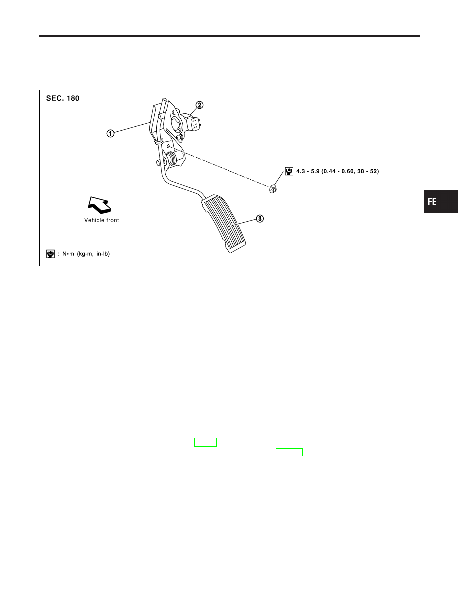
SFE748A
1.
Accelerator pedal assembly
2.
Accelerator pedal position sensor
3.
Accelerator pedal
REMOVAL
NHFE0002S01
1. Disconnect harness connector.
2. Remove mounting nut then remove accelerator pedal assembly.
CAUTION:
I
Do not disassemble accelerator pedal or remove/install accelerator pedal position sensor.
I
Do not drop or shock accelerator pedal assembly.
I
Keep accelerator pedal assembly from getting wet.
INSTALLATION
NHFE0002S02
Install in reverse order of removal.
INSPECTION AFTER INSTALLATION
NHFE0002S03
I
Check if accelerator pedal moves smoothly within its range.
I
Check if accelerator pedal returns securely to its original position.
I
Perform “Accelerator Pedal Released Position Learning” when disconnecting the accelerator pedal posi-
tion sensor harness connector. Refer to EC-70, “BASIC SERVICE PROCEDURE”.
I
For electrical inspection of accelerator pedal assembly, refer to EC-670, “DTC P2138 APP SENSOR”.
GI
MA
EM
LC
EC
AT
AX
SU
BR
ST
RS
BT
HA
SC
EL
IDX
ACCELERATOR CONTROL SYSTEM
Removal and Installation
FE-3
Removal and Installation
NHFE0004
WARNING:
When replacing fuel line parts, be sure to observe the following.
I
Put a “CAUTION: INFLAMMABLE” sign in workshop.
I
Be sure to work in a well ventilated area and furnish workshop with a CO
2
fire extinguisher.
I
Do not smoke while servicing fuel system. Keep open flames and sparks away from work area.
CAUTION:
I
Before removing fuel line parts, carry out the following procedures:
a) Put drained fuel in an explosion-proof container and put the lid on securely. Keep the container in
safe area.
b) Release fuel pressure from fuel line. Refer to EC-55, “Fuel Pressure Release”.
c) Disconnect battery ground cable.
I
Always replace O-ring and clamps with new ones.
I
Do not kink or twist tubes when they are being installed.
I
Do not tighten hose clamps excessively to avoid damaging hoses.
I
After installing fuel tubes, run engine and check for fuel leaks at connections.
a) Apply fuel pressure to fuel lines with turning ignition switch ON (with engine stopped). Then check
for fuel leaks at connections.
b) Start the engine and rev it up and check for fuel leaks at connections.
I
Use only a genuine NISSAN fuel filler cap as a replacement. If an incorrect fuel filler cap is used,
the MIL may come on.
I
For inspection and installation of EVAP system parts, refer to EC-37, “Evaporative Emission Sys-
tem”.
I
For inspection and installation of ORVR system parts, refer to EC-43, “On Board Refueling Vapor
Recovery (ORVR)”.
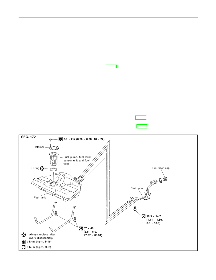
SFE749AA
FUEL SYSTEM
Removal and Installation
FE-4
Нет комментариевНе стесняйтесь поделиться с нами вашим ценным мнением.
Текст