Infiniti I35 (A33). Manual — part 503
SFE750A
SFE562A
Fuel Tank
NHFE0006
REMOVAL
NHFE0006S01
1.
Release fuel pressure from fuel line.
Refer to EC-55, “Fuel Pressure Release”.
2.
Disconnect battery ground cable.
3.
Drain fuel from fuel tank.
4.
Remove rear seat bottom. Refer to BT-53, “Removal and Instal-
lation”.
5.
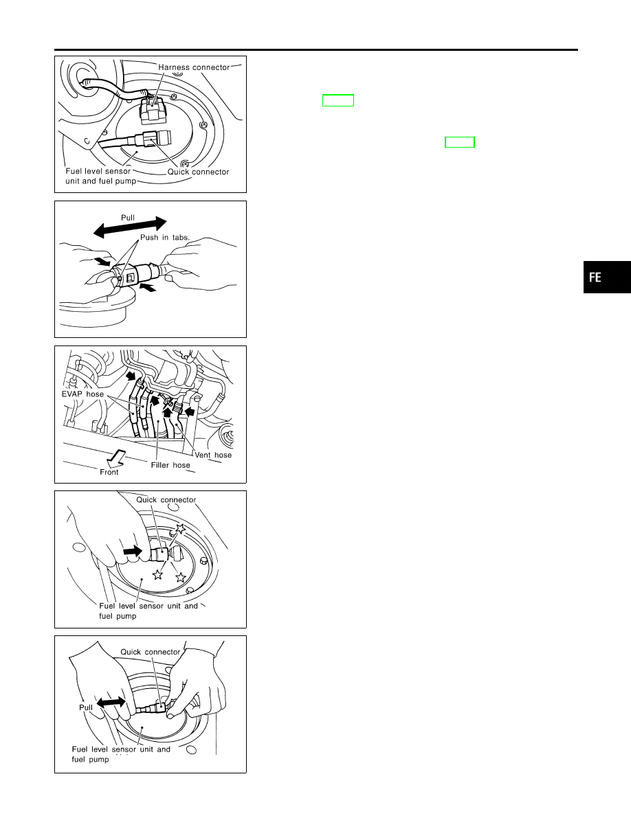
Disconnect electrical connector.
6.
Disconnect the quick connector as follows.
a.
Put mating marks on tubes and connectors for correct instal-
lation.
b.
Hold the sides of the connector, push in tabs, and pull out the
tube inserted in the retainer.
CAUTION:
I
The quick connector can be disconnected when the push
in tabs are completely depressed. Do not twist it more
than necessary.
I
Do not use any tools to disconnect the quick connector.
I
Keep clean the connecting portion of the tube and the
quick connector.
SFE559AA
7.
Disconnect filler hose, vent hose and EVAP hose at fuel tank
side.
8.
Remove exhaust heat insulators.
9.
Remove fuel tank mounting band bolts while supporting fuel
tank.
10. Remove fuel tank.
SFE751A
INSTALLATION
NHFE0006S02
To install, reverse the removal procedure. Connect the quick con-
nector as follows:
I
Align mating marks on tubes and connectors for correct instal-
lation.
I
Be sure that the connecting portion of the tube and the quick
connectors is clean and smooth.
I
Align push in tabs with retainer openings.
I
Insert tube into the center of the connector until you hear a
click.
SFE752A
After connecting quick connector, make sure the connection is
firmly made using the following method.
I
Pull on the fuel tube and connector to make sure they are firmly
connected.
Make sure that there are no leakage at fuel line connections as
follows.
I
Apply fuel pressure to fuel lines with ignition switch turned ON
(with engine stopped). Then check that there are no leaks.
I
Start the engine, increase engine speed and verify that there
are no leaks again.
GI
MA
EM
LC
EC
AT
AX
SU
BR
ST
RS
BT
HA
SC
EL
IDX
FUEL SYSTEM
Fuel Tank
FE-5
Fuel Pump, Fuel Level Sensor Unit and Fuel
Filter
NHFE0007
SFE785A
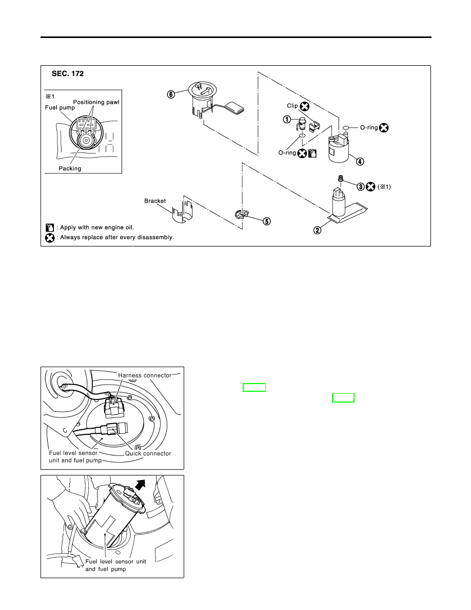
1.
Pressure regulator
2.
Fuel pump
3.
Packing
4.
Fuel filter
5.
Rubber
6.
Fuel level sensor unit
SFE750A
REMOVAL
NHFE0007S01
1.
Release fuel pressure from fuel line.
Refer to EC-55, “Fuel Pressure Release”.
2.
Remove rear seat bottom. Refer to BT-53, “Removal and Instal-
lation”.
3.
Remove inspection hole cover located under the rear seat.
4.
Disconnect electrical connector.
5.
Disconnect the quick connectors.
I
For disconnection of quick connectors, refer to step 6. of “Fuel
Tank Removal”.
6.
Remove the six bolts.
SFE755A
7.
Pull out the fuel level sensor unit and fuel pump.
I
Do not damage the arm of the fuel level sensor and fuel
tank temperature sensor.
FUEL SYSTEM
Fuel Pump, Fuel Level Sensor Unit and Fuel Filter
FE-6
SFE756A
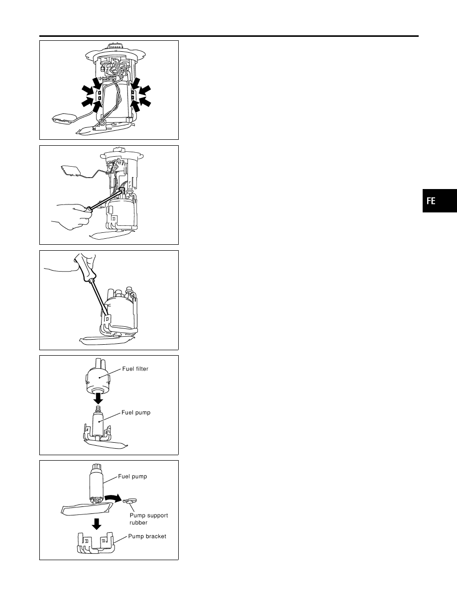
8.
Remove flange of fuel level sensor unit and fuel pump.
I
Using a screwdriver, remove the snap fit portion as shown in
the figure.
SFE757A
9.
Push fuel level sensor flange.
I
Using a screwdriver, remove the snap fit portion as shown in
the figure.
10. Pull up the fuel level sensor.
SFE758A
11. Remove fuel filter from pump bracket.
I
Using a screwdriver, remove the snap fit portion as shown in
the figure.
12. Remove pressure regulator clip, then pull out pressure regula-
tor.
SFE759A
13. Remove fuel pump, then push down the fuel pump as shown
in the figure.
14. Remove packing from fuel pump.
SFE760A
15. Remove the pump support rubber from the fuel pump.
GI
MA
EM
LC
EC
AT
AX
SU
BR
ST
RS
BT
HA
SC
EL
IDX
FUEL SYSTEM
Fuel Pump, Fuel Level Sensor Unit and Fuel Filter (Cont’d)
FE-7
INSTALLATION
NHFE0007S02
Install in the reverse order of removal paying attention to the fol-
lowing.
I
Install the fuel filter and fuel pump with the tabs aligned, make
sure a click sound of secure engagement is heard.
I
Securely connect the harness connector of the fuel pump.
I
Install the pressure regulator O-ring as follows.
CAUTION:
I
When replacing, always use a new O-ring, packing and
clip.
I
Handle it with bare hands. (Do not use gloves.)
I
Visually check the O-ring, mounting parts and mating
parts for foreign materials and flaws.
I
Before installing, apply new engine oil.
I
To avoid damage, do not apply an excessive force (pulling
or starching).
SFE765A
I
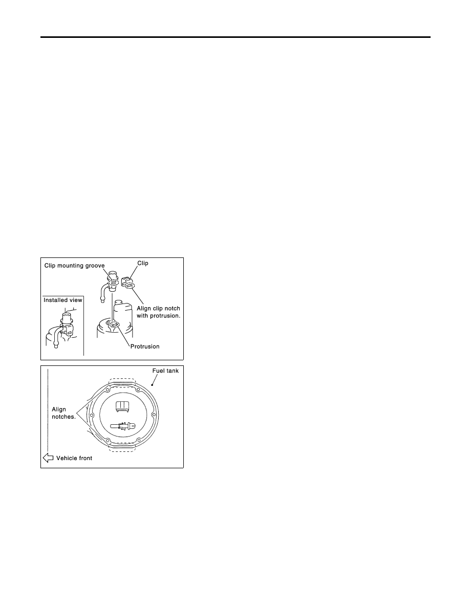
Install the pressure regulator as follows.
a)
Insert the clip to the groove of the regulator.
b)
With the clip installed, insert the regulator straight by matching
the fuel filter protrusion and the clip notch.
c)
Make sure that the fuel filter protrusion and clip notch are
securely engaged.
JFE786A
I
Install retainer so that its notch becomes parallel with notch on
fuel tank.
I
Tighten retainer mounting bolts evenly.
FUEL SYSTEM
Fuel Pump, Fuel Level Sensor Unit and Fuel Filter (Cont’d)
FE-8
Нет комментариевНе стесняйтесь поделиться с нами вашим ценным мнением.
Текст