Infiniti I35 (A33). Manual — part 374
MEL641R
GI
MA
EM
LC
EC
FE
AT
AX
SU
BR
ST
RS
BT
HA
SC
IDX
ILLUMINATION
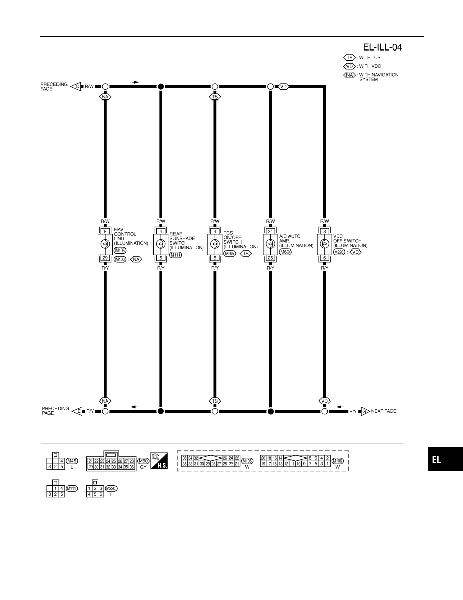
Wiring Diagram — ILL — (Cont’d)
EL-97
MEL286O
ILLUMINATION
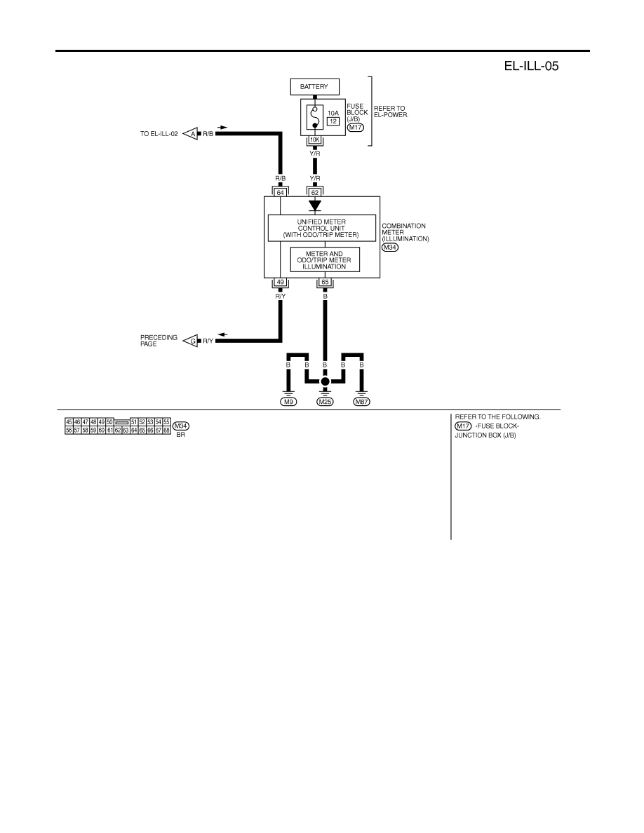
Wiring Diagram — ILL — (Cont’d)
EL-98
SEL548YA
NOTE:
For CONSULT-II Inspection Procedure, refer to “HEADLAMP (FOR USA)” (EL-46).
For CONSULT-II Application Items, refer to “HEADLAMP (FOR USA)” (EL-47).
Trouble Diagnoses for exterior lamp battery saver control, refer to “HEADLAMP (FOR USA)” (EL-47).
GI
MA
EM
LC
EC
FE
AT
AX
SU
BR
ST
RS
BT
HA
SC
IDX
ILLUMINATION
Wiring Diagram — ILL — (Cont’d)
EL-99
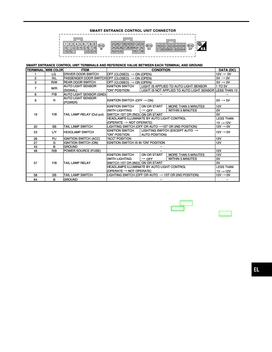
System Description
NHEL0165
POWER SUPPLY AND GROUND
NHEL0165S01
Power is supplied at all times:
I
through 10A fuse [No. 13, located in the fuse block (J/B)]
I
to key switch terminal 3 and
I
to smart entrance control unit terminal 49.
When the key is removed from ignition key cylinder, power is interrupted:
I
through key switch terminal 4
I
to smart entrance control unit terminal 25.
With the ignition switch in the ON or START position, power is supplied:
I
through 10A fuse [No. 10, located in the fuse block (J/B)]
I
to smart entrance control unit terminal 27.
Ground is supplied:
I
to smart entrance control unit terminal 43 and 64
I
through body grounds terminals M9, M25 and M87.
When the front driver side door is opened, ground is supplied:
I
through body grounds B7 (with TCS) or B78 (with VDC) and B46
I
to front door switch LH terminal 3
I
from front door switch LH terminal 2
I
to smart entrance control unit terminal 1.
When the front passenger side door is opened, ground is supplied:
I
through body grounds B106 and B127
I
to front door switch RH terminal 3
I
from front door switch RH terminal 2
I
to smart entrance control unit terminal 2.
When any other door (except front door) is opened, ground is supplied to smart entrance control unit termi-
nal 3 in the same manner as the front door switch.
When the front driver side door is unlocked by the central switch, the smart entrance control unit receives a
ground signal:
I
through body grounds terminals M9, M25 and M87
I
to front power window main switch terminal 5 or
I
to front power window switch RH terminal 7
I
from front power window main switch terminal 8 or
I
from front power window switch RH terminal 11
I
to smart entrance control unit terminal 33.
When the front driver side door is unlocked by the front door key cylinder switch, the smart entrance control
unit receives a ground signal:
I
through body grounds terminals M9, M25 and M87
I
to front door key cylinder switch LH terminal 2
I
from front door key cylinder switch LH terminal 1
I
to front power window main switch terminal 19
I
from front power window main switch terminal 8
I
to smart entrance control unit terminal 33.
When a signal, or combination of signals is received by the smart entrance control unit, ground is supplied:
I
through smart entrance control unit terminal 31
I
to interior lamp terminal 2.
With power and ground supplied, the interior lamp illuminates.
SWITCH OPERATION
NHEL0165S02
When interior lamp switch is ON, ground is supplied:
I
through case grounds of interior lamp
I
to interior lamp.
INTERIOR, STEP, SPOT, VANITY MIRROR AND TRUNK ROOM LAMPS
System Description
EL-100
Нет комментариевНе стесняйтесь поделиться с нами вашим ценным мнением.
Текст