Infiniti I35 (A33). Manual — part 372
Wiring Diagram — CORNER —
NHEL0270
MEL636R
GI
MA
EM
LC
EC
FE
AT
AX
SU
BR
ST
RS
BT
HA
SC
IDX
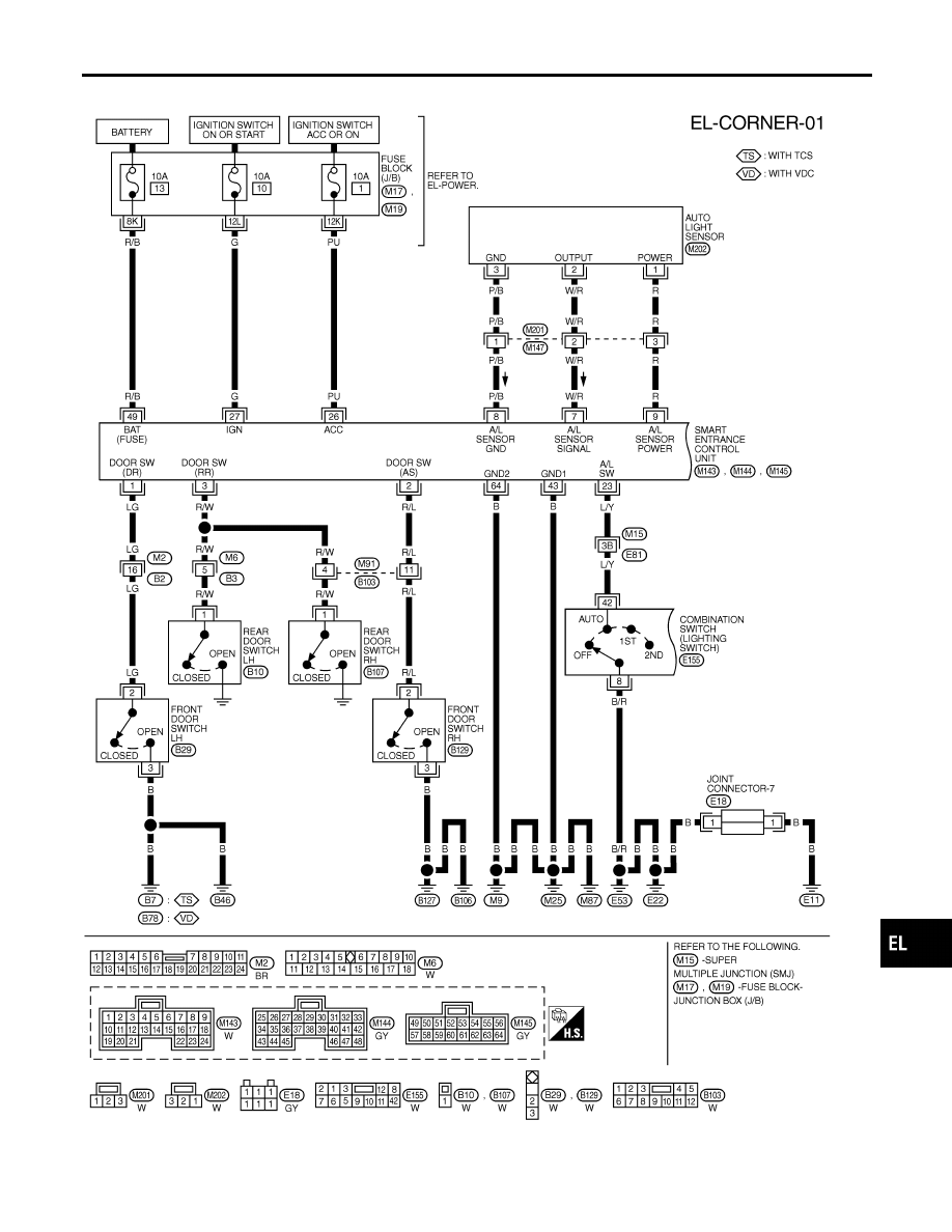
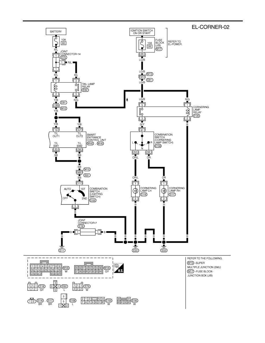
CORNERING LAMP
Wiring Diagram — CORNER —
EL-89
MEL280O
CORNERING LAMP
Wiring Diagram — CORNER — (Cont’d)
EL-90
SEL898Y
NOTE:
For CONSULT-II Inspection Procedure, refer to “HEADLAMP (FOR USA)” (EL-46).
For CONSULT-II Application Items, refer to “HEADLAMP (FOR USA)” (EL-47).
Trouble Diagnoses for exterior lamp battery saver control, refer to “HEADLAMP (FOR USA)” (EL-47).
GI
MA
EM
LC
EC
FE
AT
AX
SU
BR
ST
RS
BT
HA
SC
IDX
CORNERING LAMP
Wiring Diagram — CORNER — (Cont’d)
EL-91
System Description
NHEL0035
The illumination lamp operation is controlled by the lighting switch which is built into the combination switch
and smart entrance control unit. The battery saver system is controlled by smart entrance control unit.
Power is supplied at all times
I
to tail lamp relay terminals 1 and 3
I
through 10A fuse (No. 60, located in the fuse and fusible link box), and
I
to smart entrance control unit terminal 49
I
through 10A fuse [No. 13, located in the fuse block (J/B)].
When ignition switch is in ON or START position, power is supplied
I
to smart entrance control unit terminal 27
I
through 10A fuse [No. 10, located in the fuse block (J/B)], and
When the ignition switch is in ACC or ON position, power is supplied
I
to smart entrance control unit terminal 26
I
through 10A fuse [No. 1, located in the fuse block (J/B)].
Ground is supplied to smart entrance control unit terminals 43 and 64.
I
through body grounds M9, M25 and M87.
LIGHTING OPERATION BY LIGHTING SWITCH
NHEL0035S01
When lighting switch is 1ST (or 2ND) position, ground is supplied
I
to tail lamp relay terminal 2 from smart entrance control unit terminals 19 and 57
I
through smart entrance control unit terminals 20 and 58, and
I
through lighting switch and body grounds E11, E22 and E53.
Tail lamp relay is then energized and illumination lamps illuminate.
The lighting switch must be in the 1ST or 2ND position for illumination.
The illumination control switch that controls the amount of current to the illumination system. As the amount
of current increases, the illumination becomes brighter.
The ground for all of the components except for door mirror remote control switch, clock and grove box lamp,
ashtray are controlled through terminals 2 and 3 of the illumination control switch and body grounds M9, M25
and M87.
EXTERIOR LAMP BATTERY SAVER CONTROL
NHEL0035S02
Illumination lamps will remain on for a short while after the ignition switch is turned ON (or START) from OFF
(or ACC).
Continuity between terminals 19 and 20, and between terminals 57 and 58 of smart entrance control unit will
be disturbed after 45 seconds, then the headlamps will be turned off.
Then illumination lamps are turned off.
Exterior lamp battery saver control mode can be changed by the function setting of CONSULT-II (EL-47).
When the lighting switch is turned from OFF to 1ST (or 2ND) after illumination lamps are turned off by the
battery saver control, ground is supplied
I
to smart entrance control unit terminals 20 and 58 from lighting switch terminal 11, and
I
to tail lamp relay terminal 2 from smart entrance control unit terminals 19 and 57.
Then illumination lamps illuminate again.
ILLUMINATION
System Description
EL-92
Нет комментариевНе стесняйтесь поделиться с нами вашим ценным мнением.
Текст