Infiniti I35 (A33). Manual — part 537
SYSTEM DESCRIPTION
=NHHA0188
Component Parts
NHHA0188S01
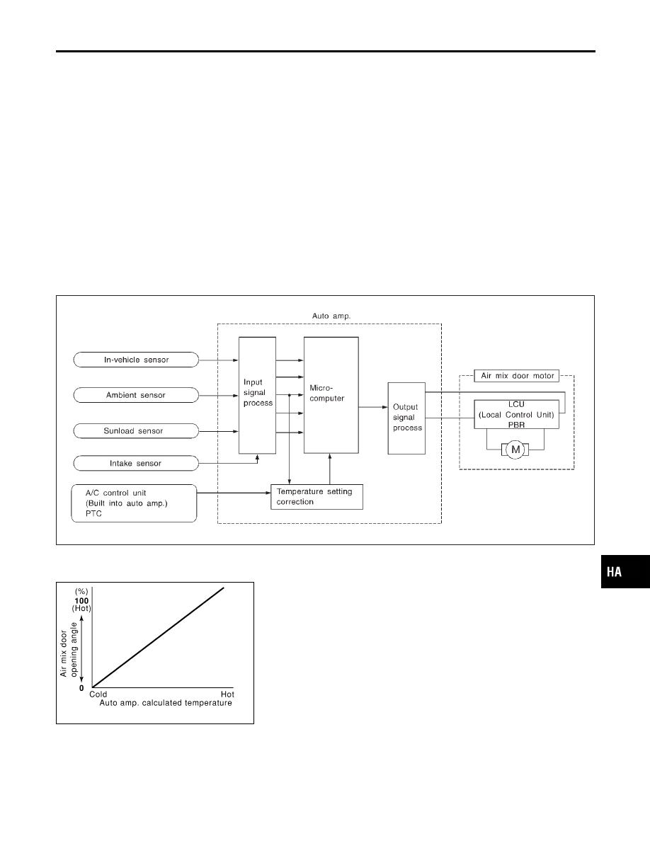
Air mix door control system components are:
1) Auto amp.
2) Air mix door motor (LCU)
3) In-vehicle sensor
4) Ambient sensor
5) Sunload sensor
6) Intake sensor
System Operation
NHHA0188S02
The auto amplifier receives data from each of the sensors. The amplifier sends air mix door, mode door, intake
door opening angle data to the air mix door motor LCU, mode door motor LCU and intake door motor LCU.
The air mix door motor, mode door motor and intake door motor read their respective signals according to the
address signal. Opening angle indication signals received from the auto amplifier and each of the motor posi-
tion sensors are compared by the LCUs in each motor with the existing decision and opening angles.
Subsequently, HOT/COLD or DEFROST/VENT operation is selected. The new selection data is returned to
the auto amplifier.
RHA424GB
Air Mix Door Control Specification
NHHA0188S03
RHA457H
GI
MA
EM
LC
EC
FE
AT
AX
SU
BR
ST
RS
BT
SC
EL
IDX
TROUBLE DIAGNOSES
Air Mix Door Motor (Cont’d)
HA-61
RHA371H
COMPONENT DESCRIPTION
NHHA0189
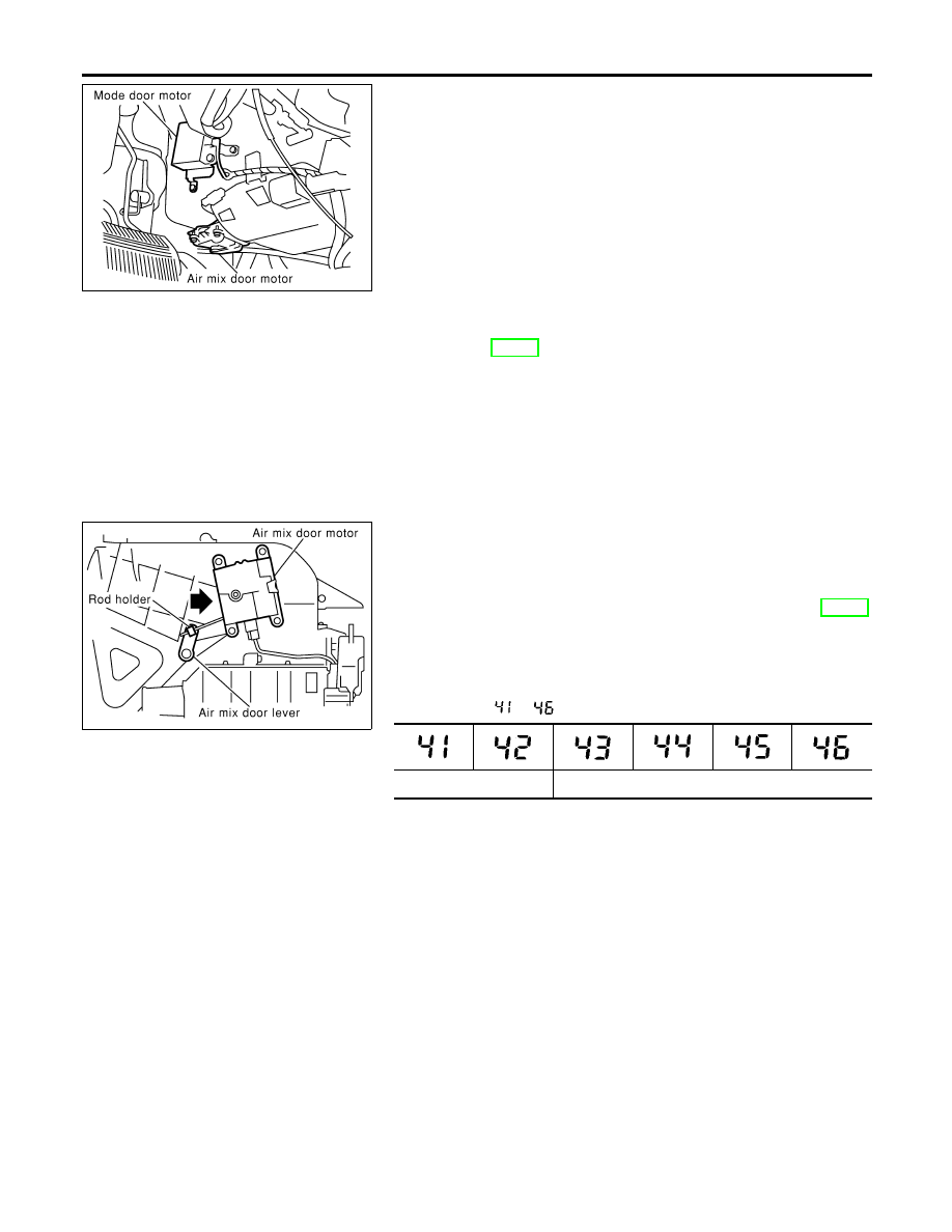
The air mix door motor is attached to the heater unit. It rotates so
that the air mix door is opened or closed to a position set by the
auto amplifier. Motor rotation is then conveyed through a shaft and
the air mix door position is then fed back to the auto amplifier by
PBR built-in air mix door motor.
DIAGNOSTIC PROCEDURE
NHHA0248
SYMPTOM: Discharge air temperature does not change.
I
Refer to HA-55.
RHA379H
CONTROL LINKAGE ADJUSTMENT
NHHA0190
Air Mix Door
NHHA0190S01
1.
Install air mix door motor on heater unit and connect it to main
harness.
2.
Set up code No. 41 in Self-diagnosis STEP-4. Refer to HA-36.
3.
Move air mix door lever by hand and hold it in full cold posi-
tion.
4.
Attach air mix door lever to rod holder.
5.
Make sure air mix door operates properly when changing from
code No.
to
by pushing DEF switch.
Full cold
Full hot
TROUBLE DIAGNOSES
Air Mix Door Motor (Cont’d)
HA-62
Intake Door Motor
TROUBLE DIAGNOSIS PROCEDURE FOR INTAKE DOOR (LAN)
=NHHA0191
SYMPTOM:
I
Intake door does not change.
I
Intake door motor does not operate normally.
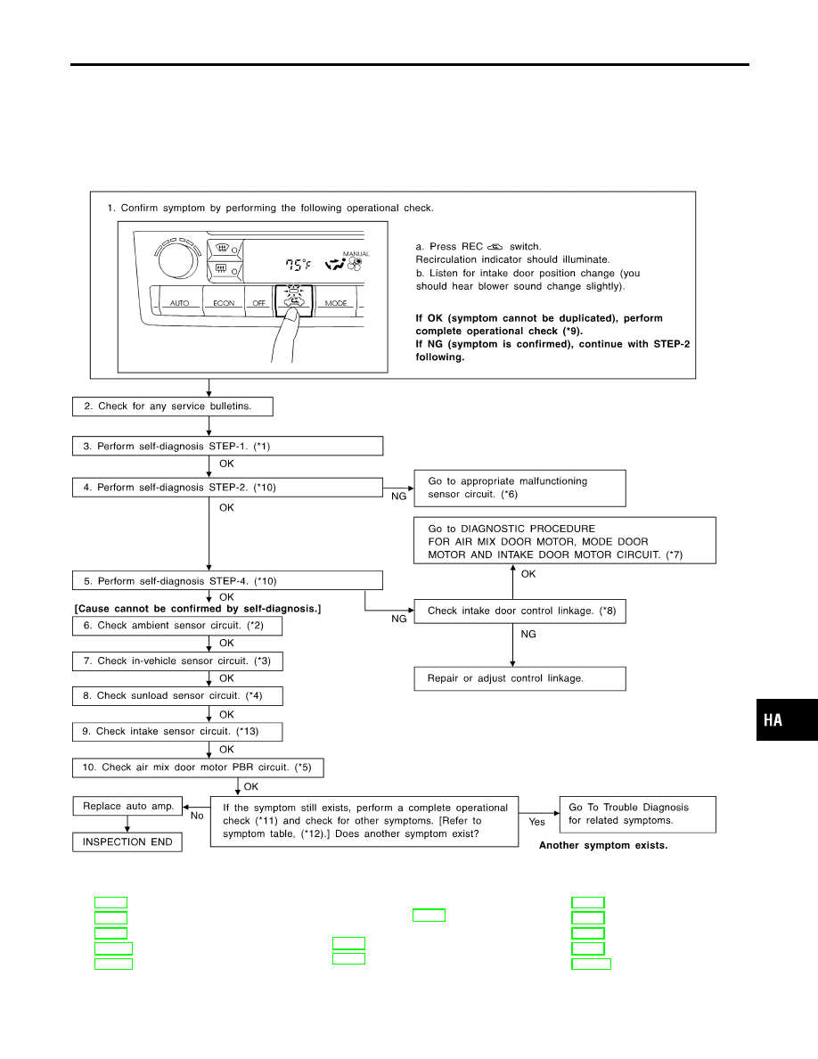
INSPECTION FLOW
RHA100I
*1: HA-36
*2: HA-93
*3: HA-97
*4: HA-100
*5: HA-106
*6: FUNCTION CONFIRMATION
PROCEDURE (HA-37), see No.
13.
*9: HA-47
*10: HA-37
*11: HA-47
*12: HA-46
*13: HA-104
GI
MA
EM
LC
EC
FE
AT
AX
SU
BR
ST
RS
BT
SC
EL
IDX
TROUBLE DIAGNOSES
Intake Door Motor
HA-63
SYSTEM DESCRIPTION
=NHHA0192
Component Parts
NHHA0192S01
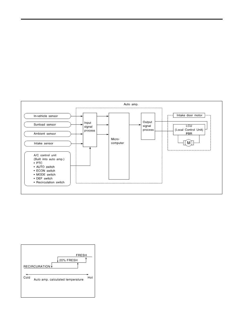
Intake door control system components are:
1)
Auto amp.
2)
Intake door motor (LCU)
3)
In-vehicle sensor
4)
Ambient sensor
5)
Sunload sensor
6)
Intake sensor
System Operation
NHHA0192S02
The intake door control determines intake door position based on
the ambient temperature, the intake air temperature and the in-ve-
hicle temperature. When the ECON, DEFROST, or OFF switches
are pushed, the auto amplifier sets the intake door at the “Fresh”
position.
RHA382HH
RHA383H
Intake Door Control Specification
NHHA0192S03
TROUBLE DIAGNOSES
Intake Door Motor (Cont’d)
HA-64
Нет комментариевНе стесняйтесь поделиться с нами вашим ценным мнением.
Текст