Infiniti I35 (A33). Manual — part 535
Mode Door Motor
TROUBLE DIAGNOSIS PROCEDURE FOR MODE DOOR MOTOR (LAN)
=NHHA0182
SYMPTOM:
I
Air outlet does not change.
I
Mode door motor does not operate normally.
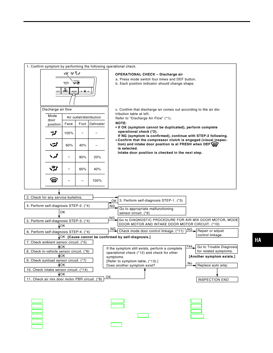
INSPECTION FLOW
RHA099IA
*1: HA-25
*2: HA-47
*3: HA-36
*4: HA-37
*5: HA-93
*6: HA-97
*7: HA-100
*8: HA-106
*9: FUNCTION CONFIRMATION
PROCEDURE (HA-37), see No.
13.
*10: HA-55
*11: HA-59
*12: HA-47
*13: HA-46
*14: HA-104
GI
MA
EM
LC
EC
FE
AT
AX
SU
BR
ST
RS
BT
SC
EL
IDX
TROUBLE DIAGNOSES
Mode Door Motor
HA-53
SYSTEM DESCRIPTION
=NHHA0183
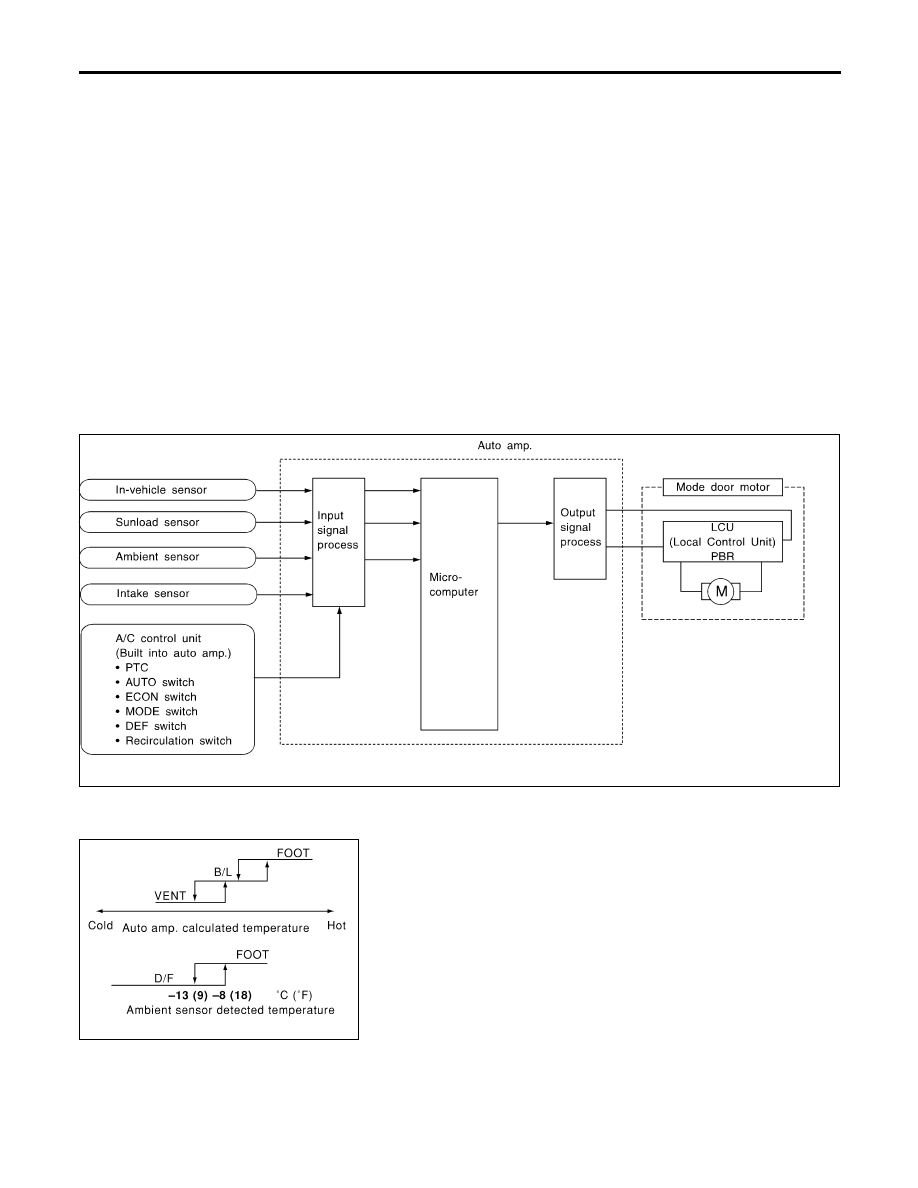
Component Parts
NHHA0183S01
Mode door control system components are:
1) Auto amp.
2) Mode door motor (LCU)
3) In-vehicle sensor
4) Ambient sensor
5) Sunload sensor
6) Intake sensor
System Operation
NHHA0183S02
The auto amplifier receives data from each of the sensors. The amplifier sends air mix door, mode door and
intake door opening angle data to the air mix door motor LCU, mode door motor LCU and intake door motor
LCU.
The air mix door motor, mode door motor and intake door motor read their respective signals according to the
address signal. Opening angle indication signals received from the auto amplifier and each of the motor posi-
tion sensors are compared by the LCUs in each motor with the existing decision and opening angles.
Subsequently, HOT/COLD or OPEN/CLOSE or DEFROST/VENT operation is selected. The new selection
data is returned to the auto amplifier.
RHA382HG
Mode Door Control Specification
NHHA0183S03
RHA384HA
TROUBLE DIAGNOSES
Mode Door Motor (Cont’d)
HA-54
RHA371H
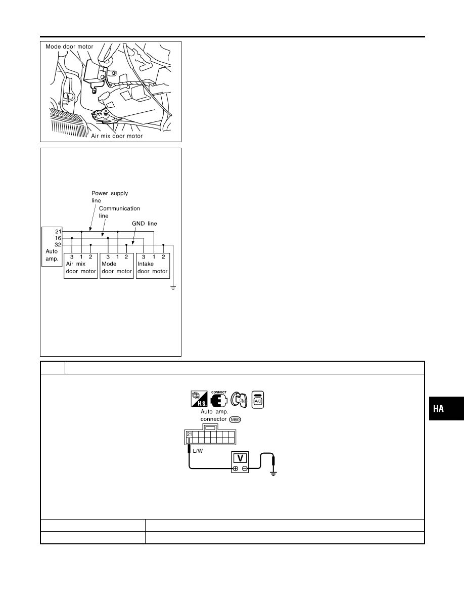
COMPONENT DESCRIPTION
NHHA0184
The mode door motor is attached to the heater unit. It rotates so
that air is discharged from the outlet set by the auto amplifier. Motor
rotation is conveyed to a link which activates the mode door.
RHA372H
DIAGNOSTIC PROCEDURE FOR AIR MIX DOOR
MOTOR, MODE DOOR MOTOR AND INTAKE DOOR
MOTOR CIRCUIT
NHHA0185
SYMPTOM: Air mix door motor, mode door motor and/or
intake door motor does not operate normally.
1
CHECK POWER SUPPLY FOR AUTO AMP. SIDE
Do approx. 12 volts exist between auto amp. harness connector M60 terminal No. 21 and ground?
RHA373H
NOTE:
If the result is NG or No after checking circuit continuity, repair harness or connector.
Yes or No
Yes
©
GO TO 2.
No
©
Replace auto amp.
GI
MA
EM
LC
EC
FE
AT
AX
SU
BR
ST
RS
BT
SC
EL
IDX
TROUBLE DIAGNOSES
Mode Door Motor (Cont’d)
HA-55
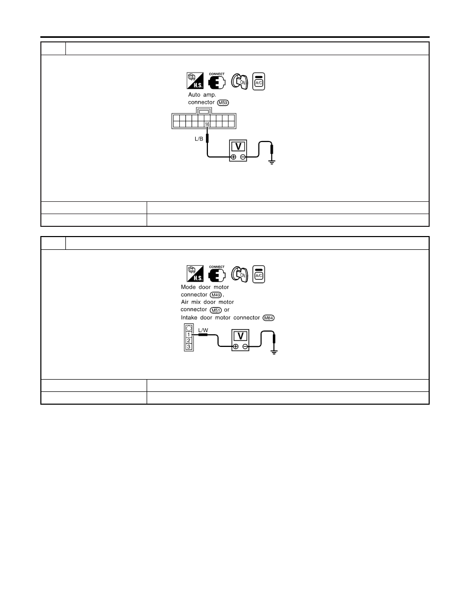
2
CHECK SIGNAL FOR AUTO AMP. SIDE
Do approx. 5.5 volts exist between auto amp. harness connector M59 terminal No. 16 and ground?
RHA374H
NOTE:
If the result is NG or No after checking circuit continuity, repair harness or connector.
Yes or No
Yes
©
GO TO 3.
No
©
Replace auto amp.
3
CHECK POWER SUPPLY FOR MOTOR SIDE
Do approx. 12 volts exist between each door motor (LCU) harness connector terminal No. 1 and ground?
RHA375HB
Yes or No
Yes
©
GO TO 4.
No
©
Repair harness or connector.
TROUBLE DIAGNOSES
Mode Door Motor (Cont’d)
HA-56
Нет комментариевНе стесняйтесь поделиться с нами вашим ценным мнением.
Текст