Infiniti I35 (A33). Manual — part 236
Diagnostic Procedure
NHEC0919
1
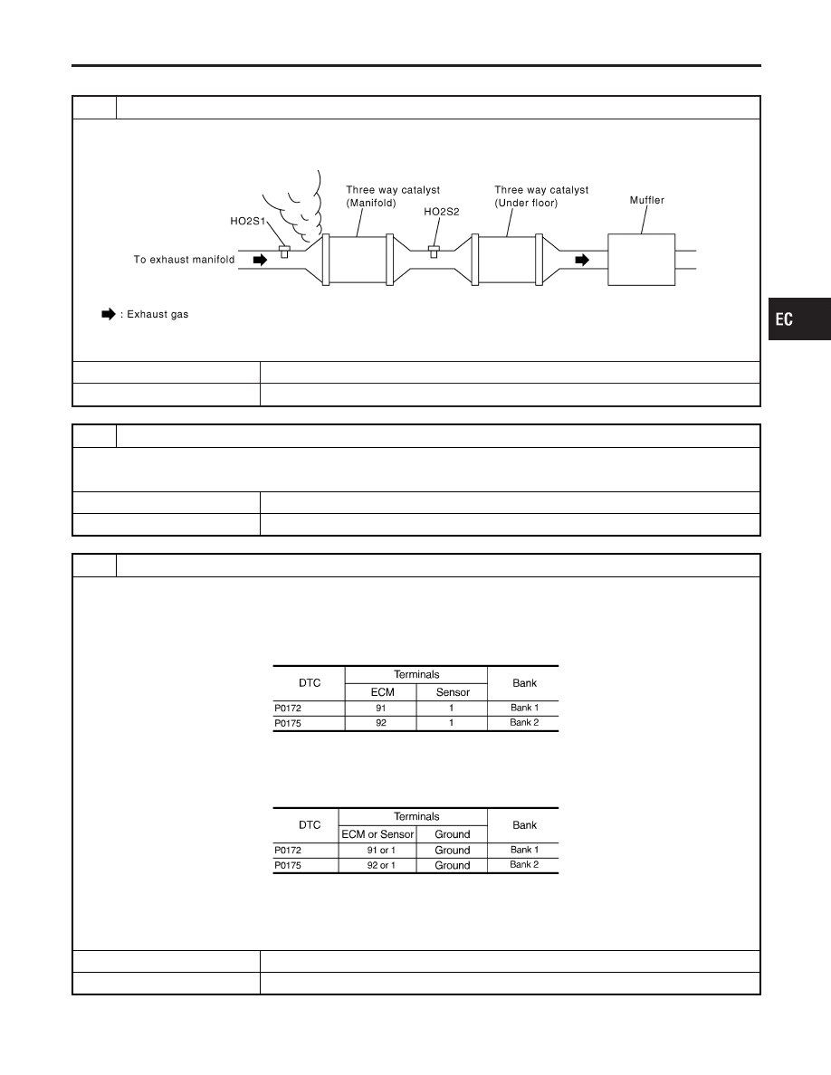
CHECK EXHAUST GAS LEAK
1. Start engine and run it at idle.
2. Listen for an exhaust gas leak before three way catalyst (manifold).
SEC502D
OK or NG
OK
©
GO TO 2.
NG
©
Repair or replace.
2
CHECK FOR INTAKE AIR LEAK
Listen for an intake air leak after the mass air flow sensor.
OK or NG
OK
©
GO TO 3.
NG
©
Repair or replace.
3
CHECK HEATED OXYGEN SENSOR 1 CIRCUIT FOR OPEN AND SHORT
1. Turn ignition switch OFF.
2. Disconnect corresponding heated oxygen sensor 1 harness connector.
3. Disconnect ECM harness connector.
4. Check harness continuity between ECM terminal and HO2S1 terminal as follows.
Refer to Wiring Diagram.
MTBL1156
Continuity should exist.
5. Check harness continuity between ECM terminal or HO2S1 terminal and ground as follows.
Refer to Wiring Diagram.
MTBL1157
Continuity should not exist.
6. Also check harness for short to power.
OK or NG
OK
©
GO TO 4.
NG
©
Repair open circuit or short to ground or short to power in harness or connectors.
GI
MA
EM
LC
FE
AT
AX
SU
BR
ST
RS
BT
HA
SC
EL
IDX
DTC P0172, P0175 FUEL INJECTION SYSTEM FUNCTION
Diagnostic Procedure
EC-285

4
CHECK FUEL PRESSURE
1. Release fuel pressure to zero. Refer to EC-55.
2. Install fuel pressure gauge and check fuel pressure. Refer to EC-55.
At idling:
Approximately 350 kPa (3.57 kg/cm
2
, 51 psi)
OK or NG
OK
©
GO TO 5.
NG
©
Follow the instruction of “Fuel Pressure Check”, EC-55.
5
CHECK MASS AIR FLOW SENSOR
With CONSULT-II
1. Install all removed parts.
2. Check “MASS AIR FLOW” in “DATA MONITOR” mode with CONSULT-II.
2.0 - 6.0 g·m/sec: at idling
7.0 - 20.0 g·m/sec: at 2,500 rpm
With GST
1. Install all removed parts.
2. Check mass air flow sensor signal in MODE 1 with GST.
2.0 - 6.0 g·m/sec: at idling
7.0 - 20.0 g·m/sec: at 2,500 rpm
OK or NG
OK
©
GO TO 6.
NG
©
Check connectors for rusted terminals or loose connections in the mass air flow sensor
circuit or engine grounds. Refer to EC-197.
DTC P0172, P0175 FUEL INJECTION SYSTEM FUNCTION
Diagnostic Procedure (Cont’d)
EC-286
6
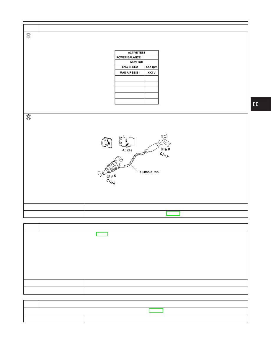
CHECK FUNCTION OF INJECTORS
With CONSULT-II
1. Start engine.
2. Perform “POWER BALANCE” in “ACTIVE TEST” mode with CONSULT-II.
SEC136D
3. Make sure that each circuit produces a momentary engine speed drop.
Without CONSULT-II
1. Start engine.
2. Listen to each injector operating sound.
MEC703B
Clicking noise should be heard.
OK or NG
OK
©
GO TO 7.
NG
©
Perform trouble diagnosis for “INJECTORS”, EC-696.
7
CHECK INJECTOR
1. Remove injector assembly. Refer to EC-56.
Keep fuel hose and all injectors connected to injector gallery.
2. Confirm that the engine is cooled down and there are no fire hazards near the vehicle.
3. Disconnect all injector harness connectors.
4. Disconnect all ignition coil harness connectors.
5. Prepare pans or saucers under each injectors.
6. Crank engine for about 3 seconds.
Make sure fuel does not drip from injector.
OK or NG
OK (Does not drip.)
©
GO TO 8.
NG (Drips.)
©
Replace the injectors from which fuel is dripping. Always replace O-ring with new one.
8
CHECK INTERMITTENT INCIDENT
Refer to “TROUBLE DIAGNOSIS FOR INTERMITTENT INCIDENT”, EC-152.
©
INSPECTION END
GI
MA
EM
LC
FE
AT
AX
SU
BR
ST
RS
BT
HA
SC
EL
IDX
DTC P0172, P0175 FUEL INJECTION SYSTEM FUNCTION
Diagnostic Procedure (Cont’d)
EC-287
SEC082D
Component Description
NHEC0773
The fuel tank temperature sensor is used to detect the fuel tem-
perature inside the fuel tank. The sensor modifies a voltage signal
from the ECM. The modified signal returns to the ECM as the fuel
temperature input. The sensor uses a thermistor which is sensitive
to the change in temperature. The electrical resistance of the ther-
mistor decreases as temperature increases.
SEF012P
<Reference data>
Fuel temperature
°C (°F)
Voltage*
V
Resistance
k
Ω
20 (68)
3.5
2.3 - 2.7
50 (122)
2.2
0.79 - 0.90
*: This data is reference value and is measured between ECM terminal 75 (Fuel
tank temperature sensor) and body ground.
CAUTION:
Do not use ECM ground terminals when measuring input/
output voltage. Doing so may result in damage to the ECM’s
transistor. Use a ground other than ECM terminals, such as
the ground.
On Board Diagnosis Logic
NHEC0774
DTC No.
Trouble diagnosis
name
DTC Detecting Condition
Possible Cause
P0181
0181
Fuel tank temperature
sensor circuit range/
performance
Rationally incorrect voltage from the sensor is sent
to ECM, compared with the voltage signals from
engine coolant temperature sensor and intake air
temperature sensor.
I
Harness or connectors
(The sensor circuit is open or
shorted.)
I
Fuel tank temperature sensor
DTC Confirmation Procedure
NHEC0776
NOTE:
If DTC Confirmation Procedure has been previously conducted,
always turn ignition switch OFF and wait at least 10 seconds before
conducting the next test.
DTC P0181 FTT SENSOR
Component Description
EC-288
Нет комментариевНе стесняйтесь поделиться с нами вашим ценным мнением.
Текст