Infiniti I35 (A33). Manual — part 280

With GST
Follow the procedure “WITH CONSULT-II” above.
GI
MA
EM
LC
FE
AT
AX
SU
BR
ST
RS
BT
HA
SC
EL
IDX
DTC P1122 ELECTRIC THROTTLE CONTROL FUNCTION
DTC Confirmation Procedure (Cont’d)
EC-461
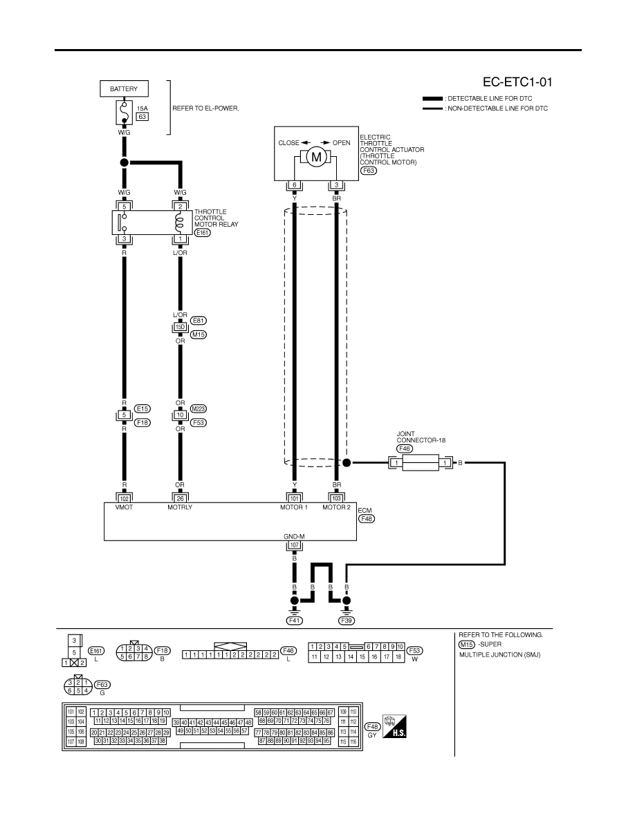
Wiring Diagram
NHEC1304
MEC359E
DTC P1122 ELECTRIC THROTTLE CONTROL FUNCTION
Wiring Diagram
EC-462
Specification data are reference values and are measured between each terminal and ground.
CAUTION:
Do not use ECM ground terminals when measuring input/output voltage. Doing so may result in dam-
age to the ECM’s transistor. Use a ground other than ECM terminals, such as the ground.
TERMI-
NAL
NO.
WIRE
COLOR
ITEM
CONDITION
DATA (DC Voltage)
26
OR
Throttle control motor
relay
[Ignition switch OFF]
BATTERY VOLTAGE
(11 - 14V)
[Ignition switch ON]
0 - 1.0V
101
Y
Throttle control motor
(Open)
[Ignition switch ON]
I
Engine stopped
I
Shift lever position is D
I
Accelerator pedal is fully depressed
0 - 14V
★
SEC037D
102
R
Throttle control motor
relay power supply
[Ignition switch ON]
BATTERY VOLTAGE
(11 - 14V)
103
BR
Throttle control motor
(Close)
[Ignition switch ON]
I
Engine stopped
I
Shift lever position is D
I
Accelerator pedal is released
0 - 14V
★
SEC038D
107
B
Throttle control motor
ground
[Engine is running]
I
Idle speed
Approximately 0V
★
: Average voltage for pulse signal (Actual pulse signal can be confirmed by oscilloscope.)
Diagnostic Procedure
NHEC1305
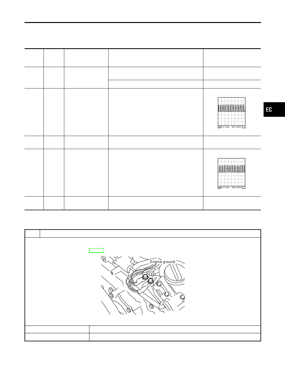
1
CHECK GROUND CONNECTIONS
1. Turn ignition switch OFF.
2. Loosen and retighten two engine ground screws.
Refer to “Ground Inspection”, EC-160.
SEC047D
OK or NG
OK
©
GO TO 2.
NG
©
Repair or replace ground connections.
GI
MA
EM
LC
FE
AT
AX
SU
BR
ST
RS
BT
HA
SC
EL
IDX
DTC P1122 ELECTRIC THROTTLE CONTROL FUNCTION
Wiring Diagram (Cont’d)
EC-463
2
CHECK THROTTLE CONTROL MOTOR GROUND CIRCUIT FOR OPEN AND SHORT
1. Disconnect ECM harness connector.
2. Check harness continuity between ECM terminal 107 and ground.
Refer to Wiring Diagram.
Continuity should exist.
3. Also check harness for short to power.
OK or NG
OK
©
GO TO 3.
NG
©
Repair open circuit or short to power in harness or connectors.
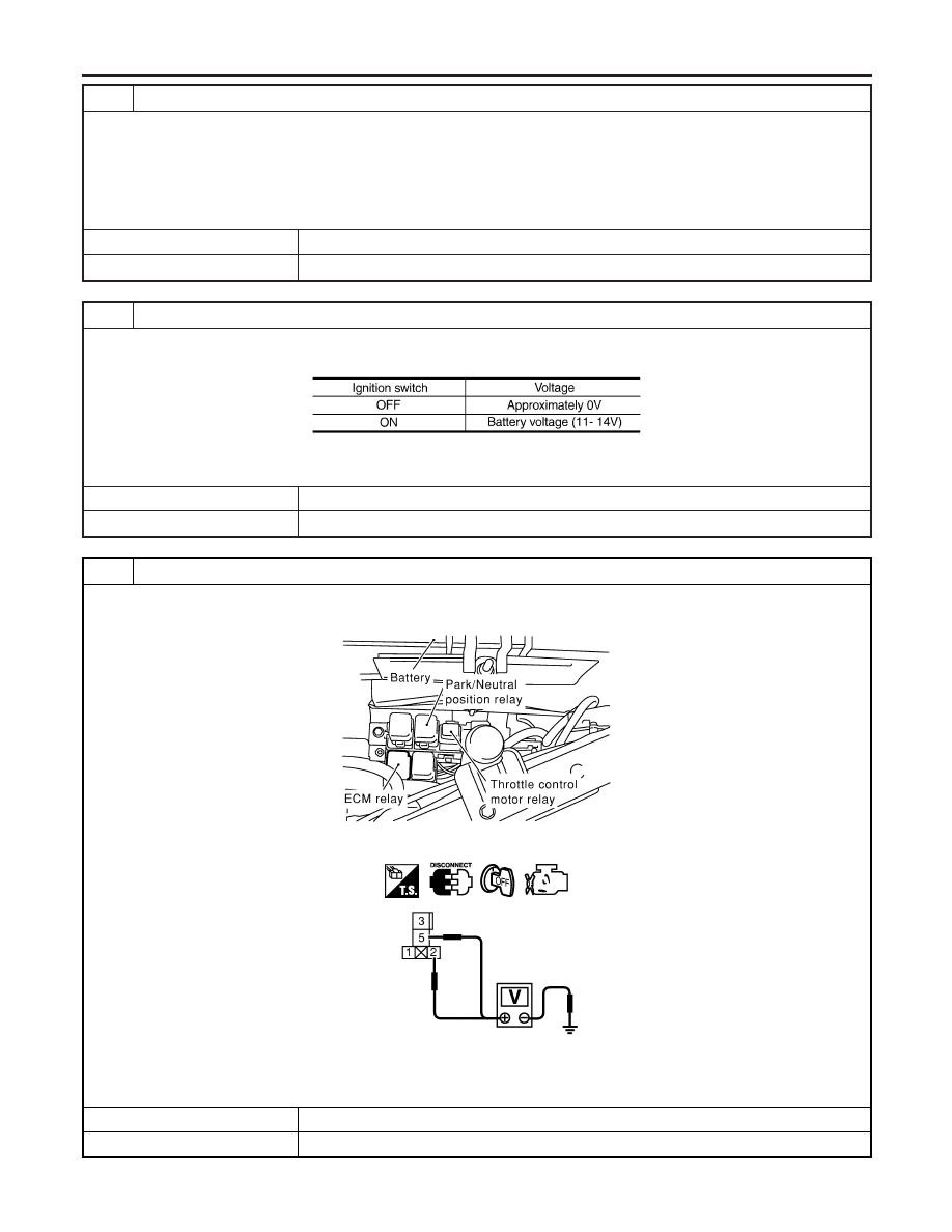
3
CHECK THROTTLE CONTROL MOTOR RELAY INPUT SIGNAL CIRCUIT FOR OPEN AND SHORT-I
1. Reconnect harness connector disconnected.
2. Check voltage between ECM terminal 102 and ground under the following conditions with CONSULT-II or tester.
MTBL1168
OK or NG
OK
©
GO TO 12.
NG
©
GO TO 4.
4
CHECK THROTTLE CONTROL MOTOR RELAY POWER SUPPLY CIRCUIT
1. Turn ignition switch OFF.
2. Disconnect throttle control motor relay.
SEC044D
3. Check voltage between throttle control motor relay terminals 2, 5 and ground with CONSULT-II or tester.
SEC091D
Voltage: Battery voltage
OK or NG
OK
©
GO TO 6.
NG
©
GO TO 5.
DTC P1122 ELECTRIC THROTTLE CONTROL FUNCTION
Diagnostic Procedure (Cont’d)
EC-464
Нет комментариевНе стесняйтесь поделиться с нами вашим ценным мнением.
Текст