Infiniti I35 (A33). Manual — part 279
6
CHECK MAF SENSOR INPUT SIGNAL CIRCUIT FOR OPEN AND SHORT
1. Check harness continuity between MAF sensor terminal 1 and ECM terminal 62.
Refer to Wiring Diagram.
Continuity should exist.
2. Also check harness for short to ground and short to power.
OK or NG
OK
©
GO TO 7.
NG
©
Repair open circuit or short to ground or short to power in harness or connectors.
7
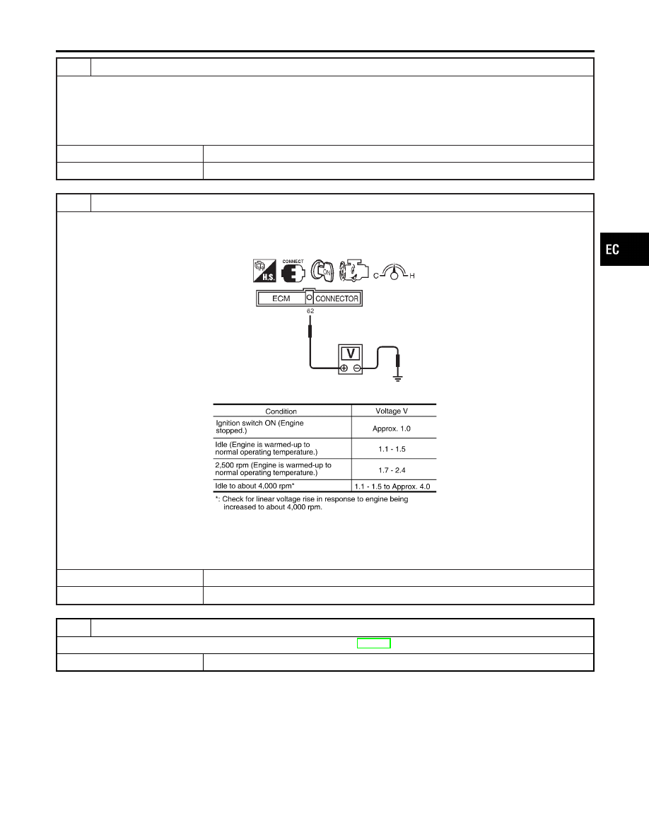
CHECK MASS AIR FLOW SENSOR
1. Reconnect harness connectors disconnected.
2. Start engine and warm it up to normal operating temperature.
3. Check voltage between ECM terminal 62 (Mass air flow sensor signal) and ground.
SEF391R
MTBL1840
4. If the voltage is out of specification, disconnect MAF sensor harness connector and connect it again.
Then repeat above check.
OK or NG
OK
©
GO TO 8.
NG
©
Replace mass air flow sensor.
8
CHECK INTERMITTENT INCIDENT
Refer to “TROUBLE DIAGNOSIS FOR INTERMITTENT INCIDENT”, EC-152.
©
INSPECTION END
GI
MA
EM
LC
FE
AT
AX
SU
BR
ST
RS
BT
HA
SC
EL
IDX
DTC P1102 MAF SENSOR
Diagnostic Procedure (Cont’d)
EC-457

Component Description
NHEC1298
Electric throttle control actuator consists of throttle control motor, throttle position sensor, etc.
The throttle control motor is operated by the ECM and it opens and closes the throttle valve.
The throttle position sensor detects the throttle valve position, and the opening and closing speed of the throttle
valve and feeds the voltage signals to the ECM. The ECM judges the current opening angle of the throttle
valve from these signals and the ECM controls the throttle control motor to make the throttle valve opening
angle properly in response to driving condition.
On Board Diagnosis Logic
NHEC1299
This self-diagnosis has the one trip detection logic.
DTC No.
Trouble diagnosis
name
DTC detecting condition
Possible cause
P1121
1121
Electric throttle control
actuator
A)
Electric throttle control actuator does not func-
tion properly due to the return spring malfunc-
tion.
I
Electric throttle control actuator
B)
Throttle valve opening angle in fail-safe mode
is not in specified range.
C)
ECM detect the throttle valve is stuck open.
FAIL-SAFE MODE
When the malfunction is detected even in the 1st trip, the ECM enters fail-safe mode and the MIL lights up.
Detected items
Engine operating condition in fail-safe mode
Malfunction A
The ECM controls the electric throttle throttle actuator by regulating the throttle opening around the idle
position. The engine speed will not rise more than 2,000 rpm.
Malfunction B
ECM controls the electric throttle control actuator by regulating the throttle opening to 20 degrees or less.
Malfunction C
While the vehicle is driving, it slows down gradually by fuel cut. After the vehicle stops, the engine stalls.
The engine can restart in N or P position, and engine speed will not exceed 1,000 rpm or more.
DTC Confirmation Procedure
NHEC1300
NOTE:
I
Perform “PROCEDURE FOR MALFUNCTION A AND B”
first. If the DTC cannot be confirmed, perform “PROCE-
DURE FOR MALFUNCTION C”.
I
If
DTC
Confirmation
Procedure
has
been
previously
conducted, always turn ignition switch OFF and wait at least 10
seconds before conducting the next test.
SEF058Y
PROCEDURE FOR MALFUNCTION A AND B
With CONSULT-II
1)
Turn ignition switch ON and wait at least 1 second.
2)
Select “DATA MONITOR” mode with CONSULT-II.
3)
Shift selector lever to D position and wait at least 3 seconds.
4)
Turn ignition switch OFF, wait at least 10 seconds.
5)
Turn ignition switch ON and wait at least 1 second.
6)
Shift selector lever to D position and wait at least 3 seconds.
7)
Turn ignition switch OFF, wait at least 10 seconds and then
turn ON.
DTC P1121 ELECTRIC THROTTLE CONTROL ACTUATOR
Component Description
EC-458
8)
If DTC is detected, go to “Diagnostic Procedure”, EC-459.
With GST
Follow the procedure “WITH CONSULT-II” above.
SEF058Y
PROCEDURE FOR MALFUNCTION C
With CONSULT-II
1)
Turn ignition switch ON and wait at least 1 second.
2)
Select “DATA MONITOR” mode with CONSULT-II.
3)
Shift selector lever to D position and wait at least 3 seconds.
4)
Shift selector lever to N or P position.
5)
Start engine and let it idle for 3 seconds.
6)
If DTC is detected, go to “Diagnostic Procedure”, EC-459.
With GST
Follow the procedure “WITH CONSULT-II” above.
Diagnostic Procedure
NHEC1413
1
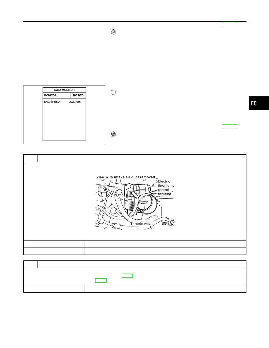
CHECK ELECTRIC THROTTLE CONTROL ACTUATOR VISUALLY
1. Remove the intake air duct.
2. Check if a foreign matter is caught between the throttle valve and the housing.
SEC083D
OK or NG
OK
©
GO TO 2.
NG
©
Remove the foreign matter and clean the electric throttle control actuator inside.
2
REPLACE ELECTRIC THROTTLE CONTROL ACTUATOR
1. Replace the electric throttle control actuator.
2. Perform “Throttle Valve Closed Position Learning”, EC-70.
3. Perform “Idle Air Volume Learning”, EC-70.
©
INSPECTION END
GI
MA
EM
LC
FE
AT
AX
SU
BR
ST
RS
BT
HA
SC
EL
IDX
DTC P1121 ELECTRIC THROTTLE CONTROL ACTUATOR
DTC Confirmation Procedure (Cont’d)
EC-459

Description
NHEC1301
NOTE:
If DTC P1122 is displayed with DTC P1121 or P1126, first perform the trouble diagnosis for DTC P1121
or P1126. Refer to EC-458, 468.
Electric throttle control actuator consists of throttle control motor, throttle position sensor, etc.
The throttle control motor is operated by the ECM and it opens and closes the throttle valve.
The current opening angle of the throttle valve is detected by the throttle position sensor and it provides the
feedback to the ECM to control the throttle control motor to make the throttle valve opening angle properly in
response to driving condition.
On Board Diagnosis Logic
NHEC1448
This self-diagnosis has the one trip detection logic.
DTC No.
Trouble diagnosis
name
DTC Detecting Condition
Possible Cause
P1122
1122
Electric throttle con-
trol performance
problem
Electric throttle control function does not operate
properly.
I
Harness or connectors
(Throttle control motor circuit is open
or shorted.)
I
Electric throttle control actuator
FAIL-SAFE MODE
When the malfunction is detected, the ECM enters fail-safe mode and the MIL lights up.
Engine operating condition in fail-safe mode
ECM stops the electric throttle control actuator control, throttle valve is maintained at a fixed opening (approx. 5 degrees) by the
return spring.
DTC Confirmation Procedure
NHEC1449
NOTE:
If DTC Confirmation Procedure has been previously conducted,
always turn ignition switch OFF and wait at least 10 seconds before
conducting the next test.
TEST CONDITION:
Before performing the following procedure, confirm that bat-
tery voltage is more than 11V when engine is running.
SEF058Y
With CONSULT-II
1)
Turn ignition switch ON and wait at least 2 seconds.
2)
Select “DATA MONITOR” mode with CONSULT-II.
3)
Start engine and let it idle for 5 seconds.
4)
If DTC is detected, go to “Diagnostic Procedure”, EC-463.
DTC P1122 ELECTRIC THROTTLE CONTROL FUNCTION
Description
EC-460
Нет комментариевНе стесняйтесь поделиться с нами вашим ценным мнением.
Текст