Infiniti I35 (A33). Manual — part 427
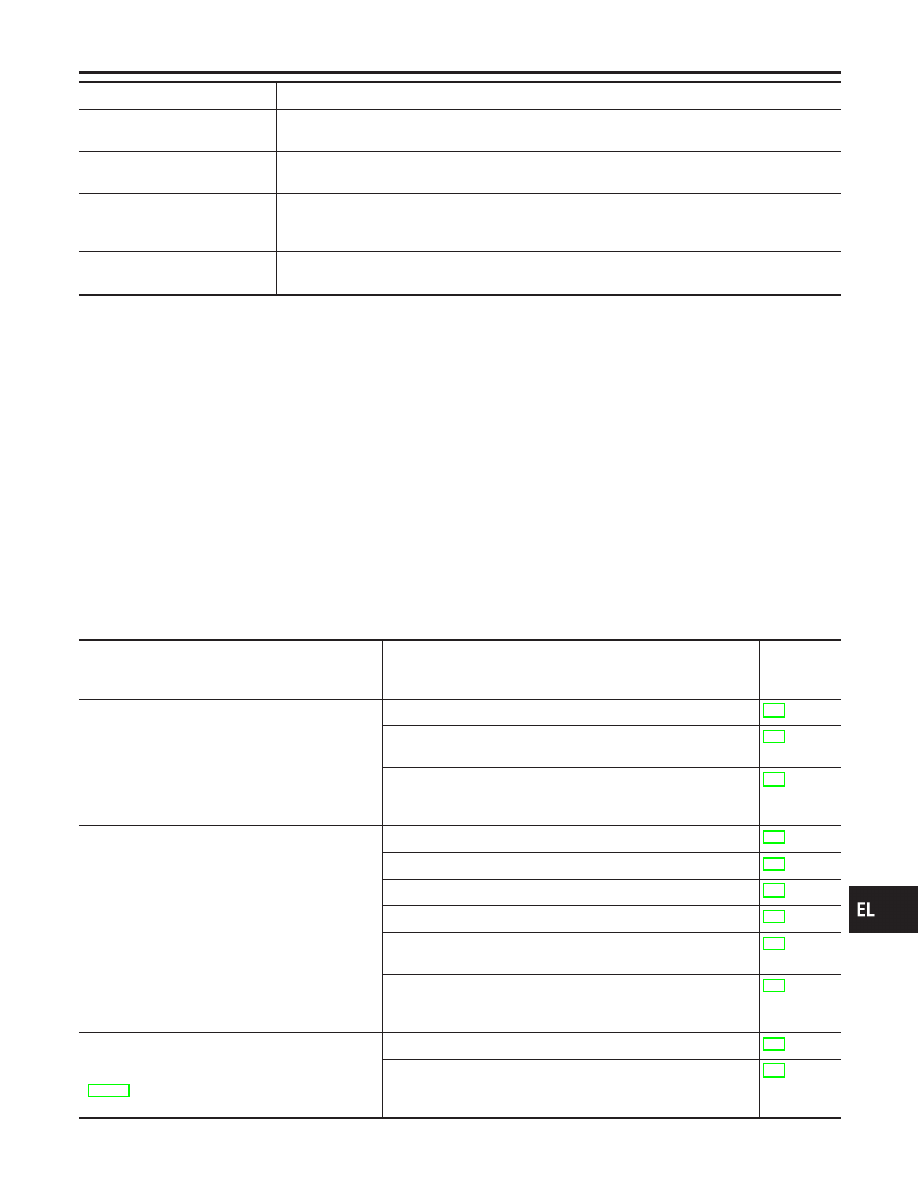
Test Item
Description
AUTO LOCK SET
Auto door lock mode can be selected among the following periods:
I
MODE 1 (5 min.)/MODE 2 (OFF-Mode)/MODE 3 (1 min.)
PANIC ALARM SET
The panic alarm button’s pressing time on keyfob can be selected among the following periods:
I
MODE 1 (0.5 sec.)/MODE 2 (OFF-Mode)/MODE 3 (1.5 sec.)
TRUNK OPENER
The trunk lid opener button’s pressing time on keyfob can be selected among the following peri-
ods:
I
MODE 1 (0.5 sec.)/MODE 2 (OFF-Mode)/MODE 3 (1.5 sec.)
PW DOWN SET
The unlock button’s pressing time on keyfob can be selected among the following periods:
I
MODE 1 (3 sec.)/MODE 2 (OFF-Mode)/MODE 3 (5 sec.)
Trouble Diagnoses
NHEL0195
SYMPTOM CHART
NHEL0195S01
NOTE:
I
Always check keyfob battery before replacing keyfob.
I
The panic alarm operation and trunk lid opener operation of
keyfob system do not activate with the ignition key inserted in
the ignition key cylinder.
Symptom
Diagnoses/service procedure
Reference
page
(EL-
)
All function of remote keyless entry system do not
operate.
1. Keyfob battery and function check
2. Power supply and ground circuit for smart entrance control
unit check
3. Replace keyfob. Refer to ID Code Entry Procedure.
NOTE: If the result of keyfob function check with CONSULT-II is
OK, keyfob is not malfunctioning.
The new ID of keyfob cannot be entered.
1. Keyfob battery and function check
2. Key switch (insert) check
3. Door switch check
4. Door lock/unlock switch LH check
5. Power supply and ground circuit for smart entrance control
unit check
6. Replace keyfob. Refer to ID Code Entry Procedure.
NOTE: If the result of keyfob function check with CONSULT-II is
OK, keyfob is not malfunctioning.
Door lock or unlock does not function.
(If the power door lock system does not operate
manually, check power door lock system. Refer to
EL-288.)
1. Keyfob battery and function check
2. Replace keyfob. Refer to ID Code Entry Procedure.
NOTE: If the result of keyfob function check with CONSULT-II is
OK, keyfob is not malfunctioning.
GI
MA
EM
LC
EC
FE
AT
AX
SU
BR
ST
RS
BT
HA
SC
IDX
REMOTE KEYLESS ENTRY SYSTEM
CONSULT-II Application Items (Cont’d)
EL-309
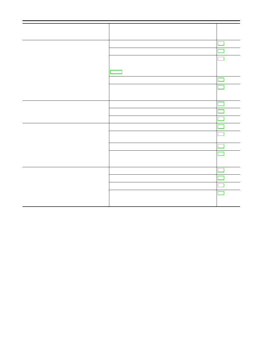
Symptom
Diagnoses/service procedure
Reference
page
(EL-
)
Hazard and horn reminder does not activate prop-
erly when pressing lock or unlock button of key-
fob.
1. Keyfob battery and function check
2. Hazard reminder check
3. Horn reminder check*
*: Horn chirp can be activated or deactivated.
First check the horn chirp setting. Refer to “System Description”,
EL-297.
4. Door switch check
5. Replace keyfob. Refer to ID Code Entry Procedure.
NOTE: If the result of keyfob function check with CONSULT-II is
OK, keyfob is not malfunctioning.
Interior lamp and key hole illumination operation
do not activate properly.
1. Interior lamp operation check
2. Key hole illumination operation check
3. Door switch check
Panic alarm (horn and headlamp) does not acti-
vate when panic alarm button is continuously
pressed.
1. Keyfob battery and function check
2. Theft warning operation check. Refer to “PRELIMINARY
CHECK” in “VEHICLE SECURITY SYSTEM”.
3. Key switch (insert) check
4. Replace keyfob. Refer to ID Code Entry Procedure.
NOTE: If the result of keyfob function check with CONSULT-II is
OK, keyfob is not malfunctioning.
Trunk lid does not open when trunk opener button
is continuously pressed.
1. Keyfob battery and function check
2. Trunk lid opener actuator check
3. Key switch (insert) check
4. Replace keyfob. Refer to ID Code Entry Procedure.
NOTE: If the result of keyfob function check with CONSULT-II is
OK, keyfob is not malfunctioning.
REMOTE KEYLESS ENTRY SYSTEM
Trouble Diagnoses (Cont’d)
EL-310
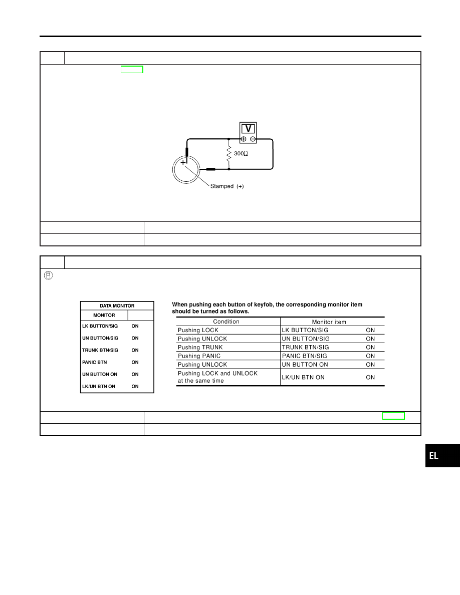
KEYFOB BATTERY AND FUNCTION CHECK
=NHEL0195S02
1
CHECK KEYFOB BATTERY
Remove battery (refer to EL-327) and measure voltage across battery positive and negative terminals, (+) and (−).
Voltage [V]:
2.5 - 3.0
NOTE:
Keyfob does not function if battery is not set correctly.
SEL237W
OK or NG
OK
©
GO TO 2.
NG
©
Replace battery.
2
CHECK KEYFOB FUNCTION
With CONSULT-II
Check keyfob function (“LK BUTTON/SIG”, “UN BUTTON/SIG”, “TRUNK BTN/SIG”, “PANIC BTN”, “UN BUTTON ON” and
“LK/UN BTN ON”) in “DATA MONITOR” mode with CONSULT-II.
SEL423Y
OK or NG
OK
©
Keyfob is OK. Further inspection is necessary. Refer to “SYMPTOM CHART”, EL-309.
NG
©
Replace keyfob. Refer to ID Code Entry Procedure.
GI
MA
EM
LC
EC
FE
AT
AX
SU
BR
ST
RS
BT
HA
SC
IDX
REMOTE KEYLESS ENTRY SYSTEM
Trouble Diagnoses (Cont’d)
EL-311
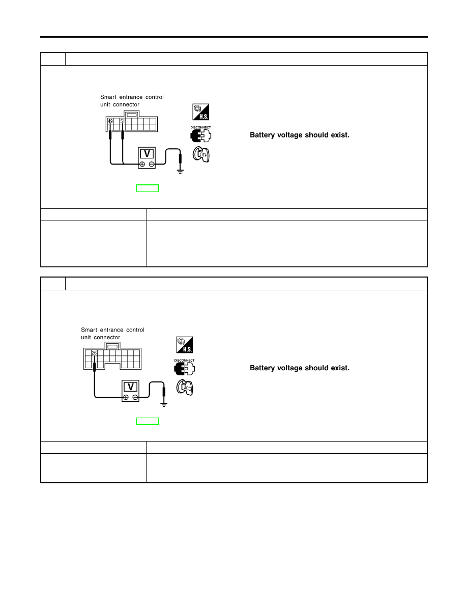
POWER SUPPLY AND GROUND CIRCUIT CHECK
=NHEL0195S03
1
CHECK MAIN POWER SUPPLY CIRCUIT FOR SMART ENTRANCE CONTROL UNIT
1. Disconnect smart entrance control unit harness connector.
2. Check voltage between smart entrance control unit harness connector M145 terminal 49 (R/B) or 51 (W/R) and ground.
SEL018Y
Refer to wiring diagram in EL-302.
OK or NG
OK
©
GO TO 2.
NG
©
Check the following.
I
40A fusible link (letter I, located in fuse and fusible link box)
I
10A fuse [No. 13, located in fuse block (J/B)]
I
E90 circuit breaker
I
Harness for open or short between smart entrance control unit and fuse
2
CHECK IGNITION SWITCH “ACC” CIRCUIT
1. Disconnect smart entrance control unit harness connector.
2. Check voltage between smart entrance control unit harness connector M144 terminal 26 (PU) and ground while ignition
switch is “ACC”.
SEL019Y
Refer to wiring diagram in EL-302.
OK or NG
OK
©
GO TO 3.
NG
©
Check the following.
I
10A fuse [No. 1, located in fuse block (J/B)]
I
Harness for open or short between smart entrance control unit and fuse
REMOTE KEYLESS ENTRY SYSTEM
Trouble Diagnoses (Cont’d)
EL-312
Нет комментариевНе стесняйтесь поделиться с нами вашим ценным мнением.
Текст