Infiniti I35 (A33). Manual — part 332
5
CHECK THROTTLE POSITION SENSOR INPUT SIGNAL CIRCUIT FOR OPEN AND SHORT
1. Check harness continuity between ECM terminal 83 and electric throttle control actuator terminal 4, ECM terminal 84
and electric throttle control actuator terminal 2.
Refer to Wiring Diagram.
Continuity should exist.
2. Also check harness for short to ground and short to power.
OK or NG
OK
©
GO TO 6.
NG
©
Repair open circuit or short to ground or short to power in harness or connectors.
6
CHECK THROTTLE POSITION SENSOR
Refer to “Component Inspection”, EC-669.
OK or NG
OK
©
GO TO 8.
NG
©
GO TO 7.
7
REPLACE ELECTRIC THROTTLE CONTROL ACTUATOR
1. Replace the electric throttle control actuator.
2. Perform “Throttle Valve Closed Position Learning”, EC-70.
3. Perform “Idle Air Volume Learning”, EC-70.
©
INSPECTION END
8
CHECK INTERMITTENT INCIDENT
Refer to “TROUBLE DIAGNOSIS FOR INTERMITTENT INCIDENT”, EC-152.
©
INSPECTION END
SEC900C
Component Inspection
NHEC1371
THROTTLE POSITION SENSOR
1.
Reconnect all harness connectors disconnected.
2.
Perform “Throttle Valve Closed Position Learning”, EC-70.
3.
Turn ignition switch ON.
4.
Set selector lever to D position.
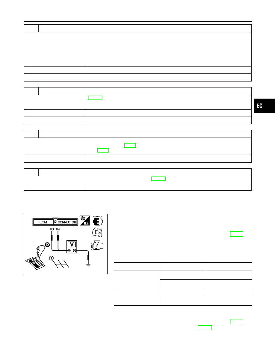
5.
Check voltage between ECM terminals 83 (TP sensor 1), 84
(TP sensor 2) and ground under the following conditions.
Terminal
Accelerator pedal
Voltage
83
(Throttle position sensor
1)
Released
More than 0.36V
Fully depressed
Less than 4.75V
84
(Throttle position sensor
2)
Released
Less than 4.75V
Fully depressed
More than 0.36V
6.
If NG, replace electric throttle control actuator and go to the
next step.
7.
Perform “Throttle Valve Closed Position Learning”, EC-70.
8.
Perform “Idle Air Volume Learning”, EC-70.
GI
MA
EM
LC
FE
AT
AX
SU
BR
ST
RS
BT
HA
SC
EL
IDX
DTC P2135 TP SENSOR
Diagnostic Procedure (Cont’d)
EC-669
PBIB1741E
Component Description
NHEC1379
The accelerator pedal position sensor is installed on the upper end
of the accelerator pedal assembly. The sensor detects the accel-
erator position and sends a signal to the ECM.
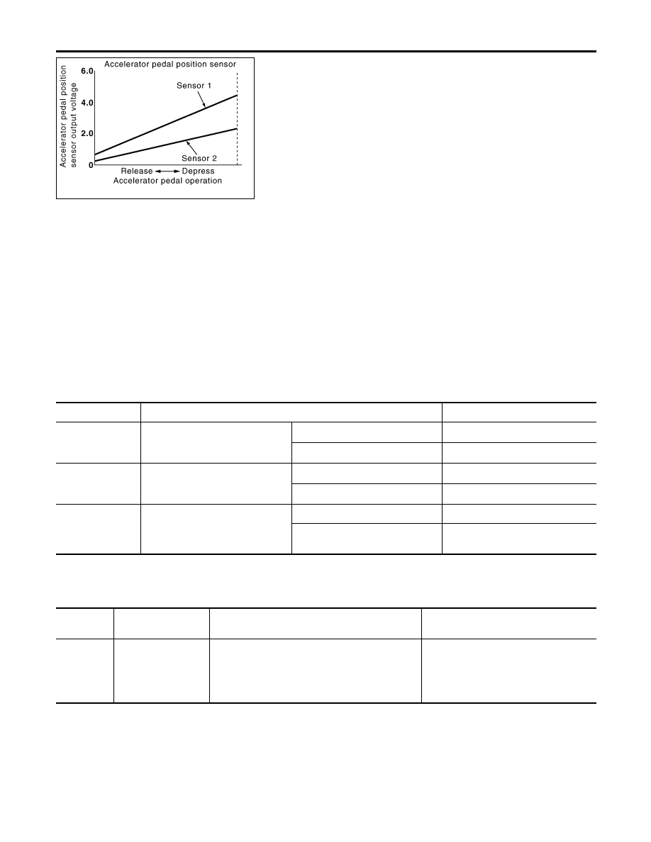
Accelerator pedal position sensor has two sensors. These sensors
are a kind of potentiometers which transform the accelerator pedal
position into output voltage, and emit the voltage signal to the ECM.
In addition, these sensors detect the opening and closing speed of
the accelerator pedal and feed the voltage signals to the ECM. The
ECM judges the current opening angle of the accelerator pedal
from these signals and controls the throttle control motor based on
these signals.
Idle position of the accelerator pedal is determined by the ECM
receiving the signal from the accelerator pedal position sensor. The
ECM uses this signal for the engine operation such as fuel cut.
CONSULT-II Reference Value in Data Monitor
Mode
NHEC1380
Specification data are reference values.
MONITOR ITEM
CONDITION
SPECIFICATION
ACCEL SEN1
I
Ignition switch: ON
(engine stopped)
I
Shift lever: D
Accelerator pedal: Released
0.41 - 0.71V
Accelerator pedal: Fully depressed
More than 3.7V
ACCEL SEN2*
I
Ignition switch: ON
(engine stopped)
I
Shift lever: D
Accelerator pedal: Released
0.15 - 0.97V
Accelerator pedal: Fully depressed
More than 3.5V
CLSD THL POS
I
Ignition switch: ON
(engine stopped)
I
Shift lever: D
Accelerator pedal: Released
ON
Accelerator pedal: Slightly
depressed
OFF
*: Accelerator pedal position sensor 2 signal is converted by ECM internally. Thus, it differs from ECM terminal voltage signal.
On Board Diagnosis Logic
NHEC1438
This self-diagnosis has the one trip detection logic.
DTC No.
Trouble diagnosis
name
DTC Detecting Condition
Possible Cause
P2138
2138
Accelerator pedal
position sensor circuit
range/performance
problem
Rationally incorrect voltage is sent to ECM com-
pared with the signals from APP sensor 1 and
APP sensor 2.
I
Harness or connector
(The APP sensor 1 and 2 circuit is
open or shorted.)
I
Accelerator pedal position sensor 1
and 2
DTC P2138 APP SENSOR
Component Description
EC-670
FAIL-SAFE MODE
=NHEC1438S01
When the malfunction is detected, ECM enters fail-safe mode and the MIL lights up.
Engine operation condition in fail-safe mode
The ECM controls the electric throttle control actuator in regulating the throttle opening in order for the idle position to be within
+10 degrees.
The ECM regulates the opening speed of the throttle valve to be slower than the normal condition.
So, the acceleration will be poor.
DTC Confirmation Procedure
NHEC1439
NOTE:
If DTC Confirmation Procedure has been previously conducted,
always turn ignition switch OFF and wait at least 10 seconds before
conducting the next test.
TESTING CONDITION:
Before performing the following procedure, confirm that bat-
tery voltage is more than 10V at idle.
SEF058Y
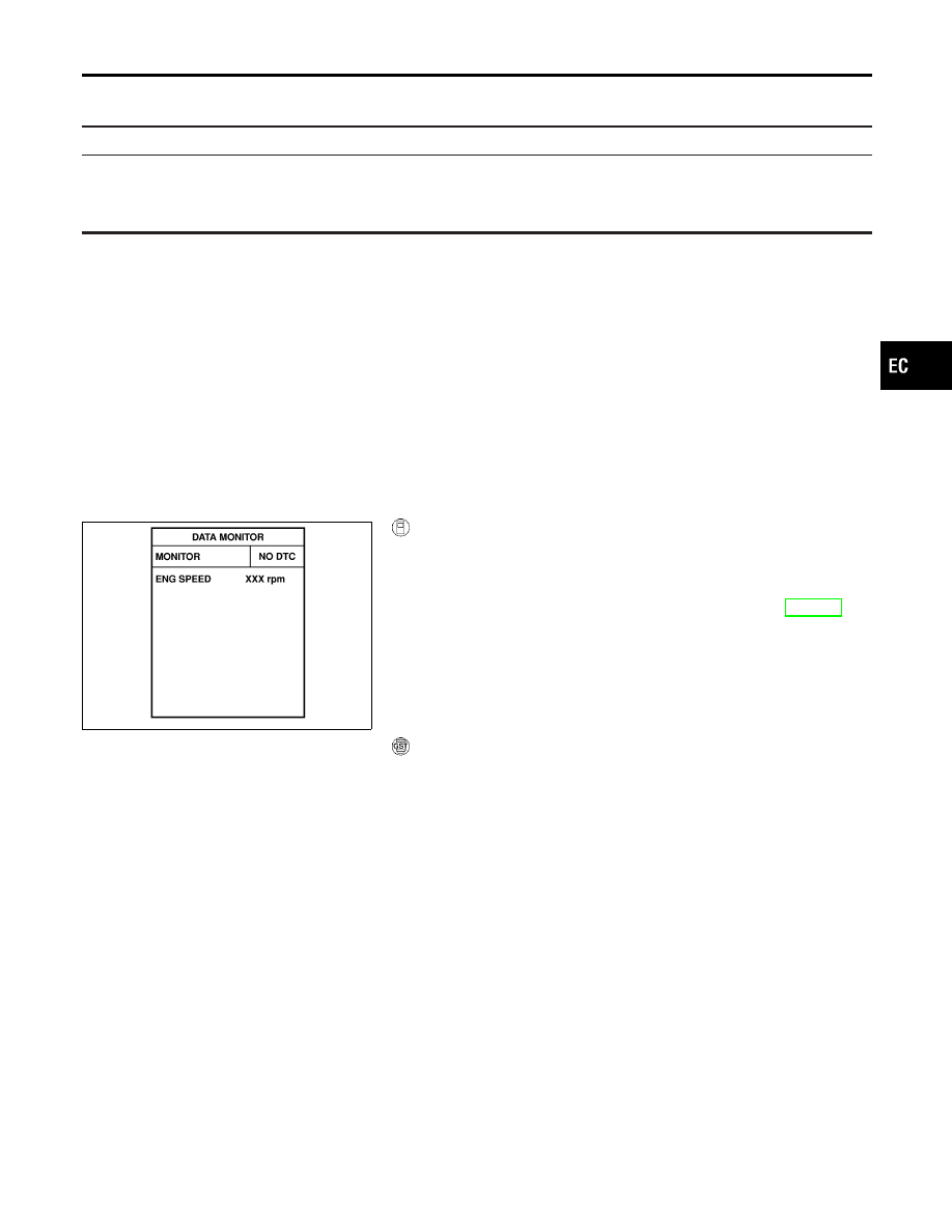
With CONSULT-II
1.
Turn ignition switch ON.
2.
Select “DATA MONITOR” mode with CONSULT-II.
3.
Start engine and let it idle for 1 second.
4.
If DTC is detected, go to “Diagnostic Procedure”, EC-673.
With GST
Follow the procedure “WITH CONSULT-II” above.
GI
MA
EM
LC
FE
AT
AX
SU
BR
ST
RS
BT
HA
SC
EL
IDX
DTC P2138 APP SENSOR
On Board Diagnosis Logic (Cont’d)
EC-671
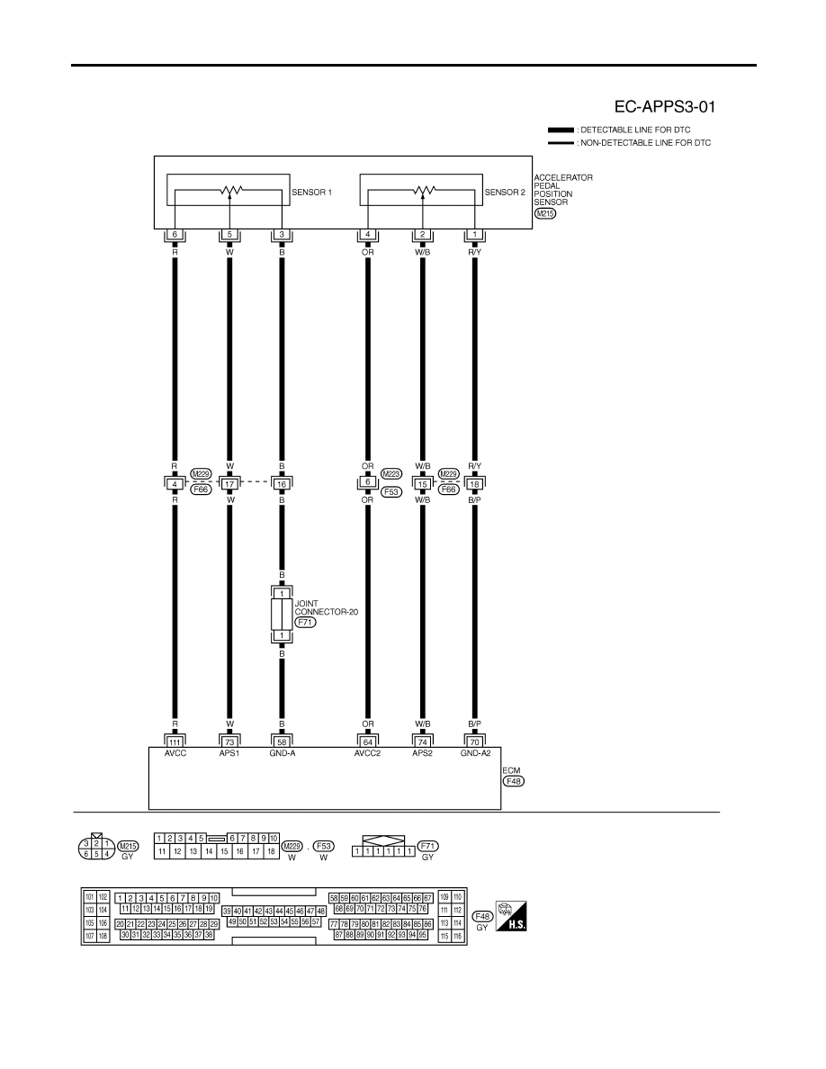
Wiring Diagram
NHEC1383
MEC645E
DTC P2138 APP SENSOR
Wiring Diagram
EC-672
Нет комментариевНе стесняйтесь поделиться с нами вашим ценным мнением.
Текст