Infiniti I35 (A33). Manual — part 82
SAT086F
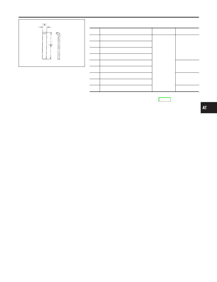
Retainer Plate (Upper body)
NHAT0140S02
Unit: mm (in)
No.
Name of control valve
Width A
Length B
22
Pilot valve
6.0 (0.236)
21.5 (0.846)
30
1st reducing valve
34
3-2 timing valve
17
Torque converter relief valve
9
1-2 accumulator valve
38.5 (1.516)
25
1-2 accumulator piston valve
21
Overrun clutch reducing valve
24.0 (0.945)
5
Cooler check valve
14
Torque converter clutch control valve
28.0 (1.102)
I
Install proper retainer plates.
Refer to “Control Valve Upper Body”, AT-322.
GI
MA
EM
LC
EC
FE
AX
SU
BR
ST
RS
BT
HA
SC
EL
IDX
REPAIR FOR COMPONENT PARTS
Control Valve Upper Body (Cont’d)
AT-325
Control Valve Lower Body
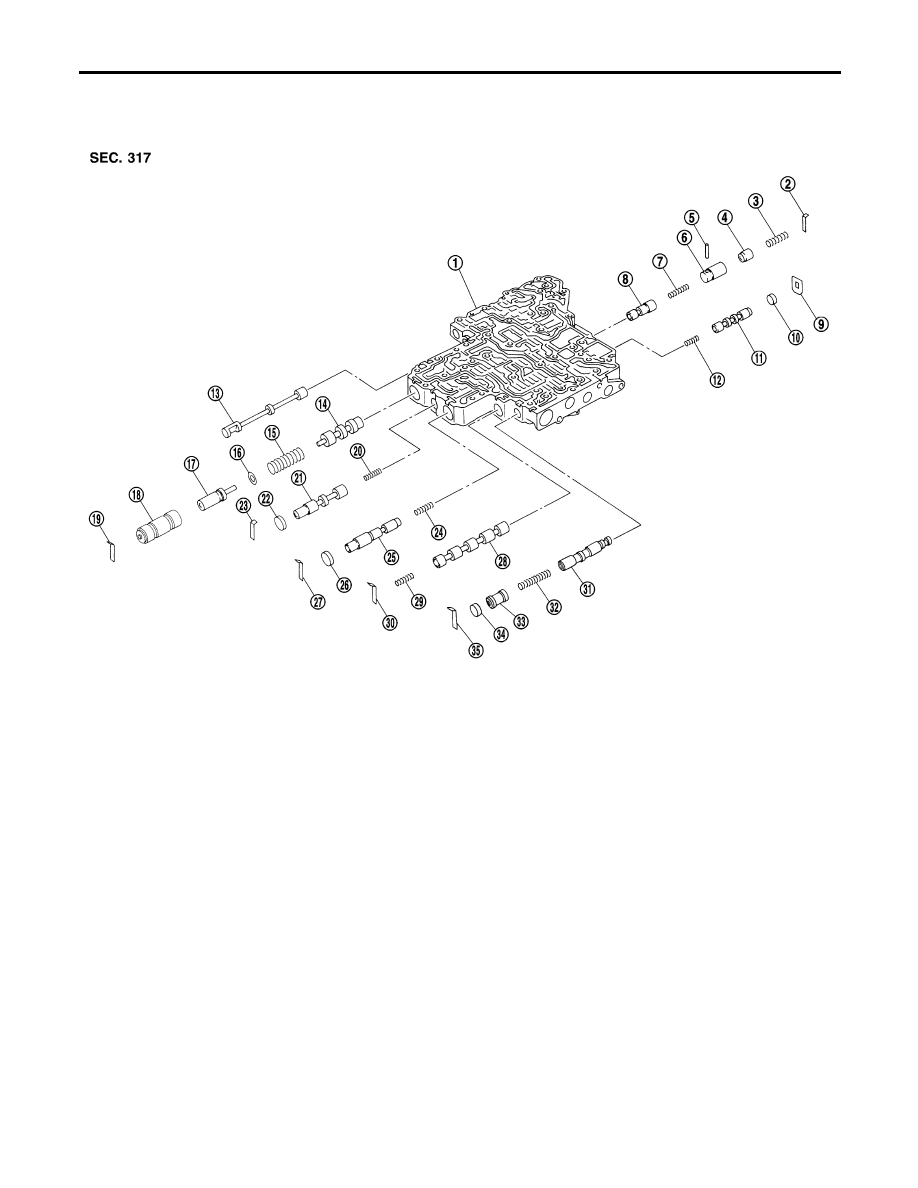
COMPONENTS
=NHAT0141
Apply ATF to all components before installation.
SAT773J
1.
Lower body
2.
Retainer plate
3.
Return spring
4.
Piston
5.
Parallel pin
6.
Sleeve
7.
Return spring
8.
Pressure modifier valve
9.
Retainer plate
10. Plug
11. Shift valve B
12. Return spring
13. Manual valve
14. Pressure regulator valve
15. Return spring
16. Spring seat
17. Plug
18. Sleeve
19. Retainer plate
20. Return spring
21. Overrun clutch control valve
22. Plug
23. Retainer plate
24. Return spring
25. Accumulator control valve
26. Plug
27. Retainer plate
28. Shift valve A
29. Return spring
30. Retainer plate
31. Shuttle valve
32. Return spring
33. Plug
34. Plug
35. Retainer plate
REPAIR FOR COMPONENT PARTS
Control Valve Lower Body
AT-326
SAT550G
DISASSEMBLY
NHAT0142
I
Remove valves at retainer plate.
For removal procedures, refer to “DISASSEMBLY”, “Control
Valve Upper Body”, AT-323.
SAT138D
INSPECTION
NHAT0143
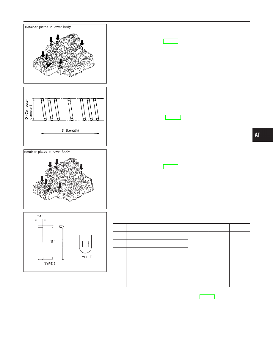
Valve Springs
NHAT0143S01
I
Check each valve spring for damage or deformation. Also
measure free length and outer diameter.
Inspection standard:
Refer to SDS, AT-382.
I
Replace valve springs if deformed or fatigued.
Control Valves
NHAT0143S02
I
Check sliding surfaces of control valves, sleeves and plugs for
damage.
SAT550A
ASSEMBLY
NHAT0144
I
Install control valves.
For installation procedures, refer to “ASSEMBLY”, “Control
Valve Upper Body”, AT-324.
SAT089F
Retainer Plate (Lower body)
NHAT0144S01
Unit: mm (in)
No.
Name of control valve and plug
Width A
Length B
Type
19
Pressure regulator valve
6.0
(0.236)
28.0
(1.102)
I
27
Accumulator control valve
30
Shift valve A
23
Overrun clutch control valve
2
Pressure modifier valve
35
Shuttle valve
9
Shift valve B
—
—
II
I
Install proper retainer plates.
Refer to “Control Valve Lower Body”, AT-326.
GI
MA
EM
LC
EC
FE
AX
SU
BR
ST
RS
BT
HA
SC
EL
IDX
REPAIR FOR COMPONENT PARTS
Control Valve Lower Body (Cont’d)
AT-327
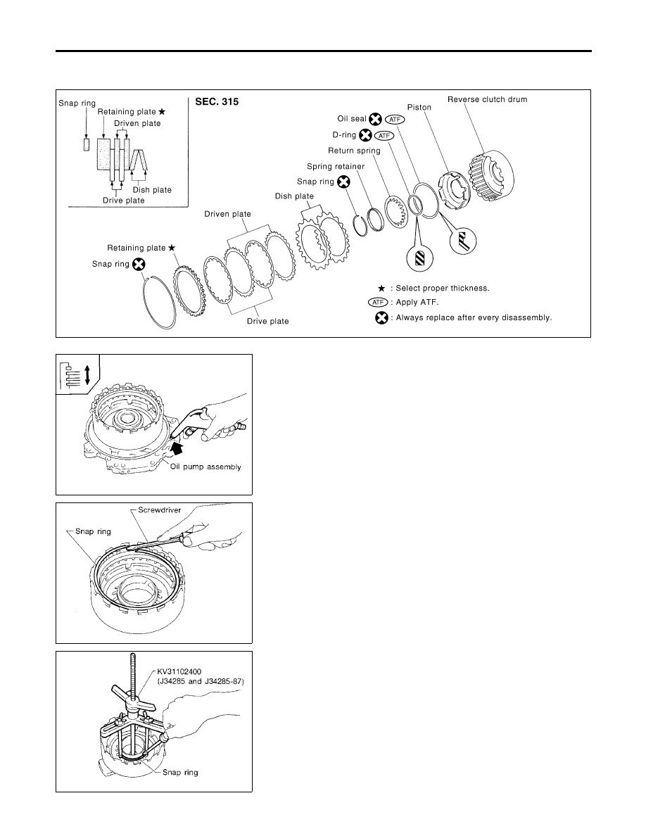
Reverse Clutch
COMPONENTS
NHAT0145
SAT843K
SAT092F
DISASSEMBLY
NHAT0146
1.
Check operation of reverse clutch
a.
Install seal ring onto drum support of oil pump cover and install
reverse clutch assembly. Apply compressed air to oil hole.
b.
Check to see that retaining plate moves to snap ring.
c.
If retaining plate does not contact snap ring:
I
D-ring might be damaged.
I
Oil seal might be damaged.
I
Fluid might be leaking past piston check ball.
SAT093F
2.
Remove snap ring.
3.
Remove drive plates, driven plates, retaining plate, and dish
plates.
SAT094F
4.
Set Tool on spring retainer and remove snap ring from reverse
clutch drum while compressing return springs.
I
Set Tool directly over springs.
I
Do not expand snap ring excessively.
5.
Remove spring retainer and return springs.
REPAIR FOR COMPONENT PARTS
Reverse Clutch
AT-328
Нет комментариевНе стесняйтесь поделиться с нами вашим ценным мнением.
Текст