Infiniti I35 (A33). Manual — part 337
Specification data are reference values and are measured between each terminal and ground.
CAUTION:
Do not use ECM ground terminals when measuring input/output voltage. Doing so may result in dam-
age to the ECM’s transistor. Use a ground other than ECM terminals, such as the ground.
TERMI-
NAL
NO.
WIRE
COLOR
ITEM
CONDITION
DATA (DC Voltage)
5
6
7
15
16
17
Y/R
G/R
L/R
GY
PU/W
GY/R
Ignition signal No. 1
Ignition signal No. 2
Ignition signal No. 3
Ignition signal No. 4
Ignition signal No. 5
Ignition signal No. 6
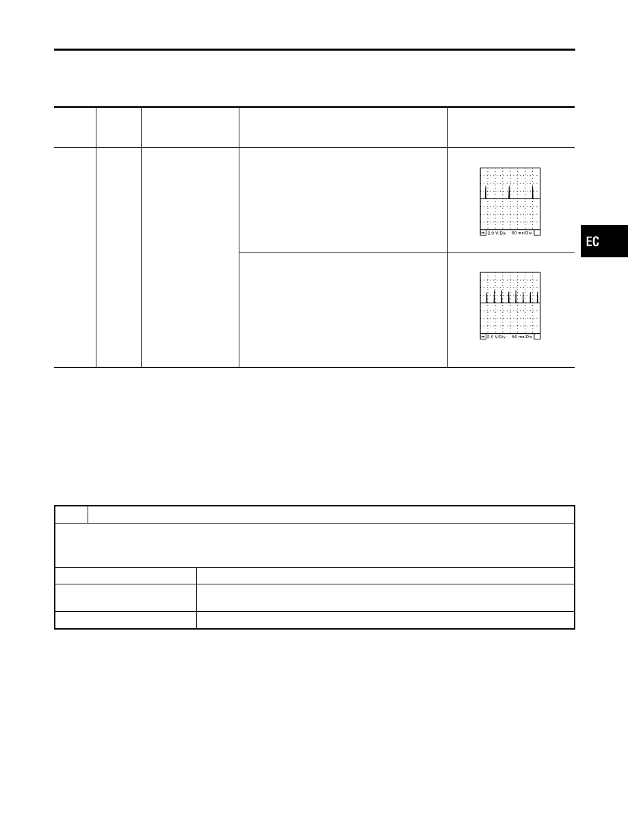
[Engine is running]
I
Warm-up condition
I
Idle speed
NOTE:
The pulse cycle changes depending on rpm at idle.
0 - 0.2V
★
SEC986C
[Engine is running]
I
Warm-up condition
I
Engine speed is 2,500 rpm.
0.1 - 0.3V
★
SEC987C
★
: Average voltage for pulse signal (Actual pulse signal can be confirmed by oscilloscope.)
Diagnostic Procedure
NHEC0820
1
CHECK ENGINE START
Turn ignition switch OFF, and restart engine.
Is engine running?
Yes or No
Yes (With CONSULT-II)
©
GO TO 2.
Yes (Without CONSULT-
II)
©
GO TO 3.
No
©
GO TO 4.
GI
MA
EM
LC
FE
AT
AX
SU
BR
ST
RS
BT
HA
SC
EL
IDX
IGNITION SIGNAL
Wiring Diagram (Cont’d)
EC-689
2
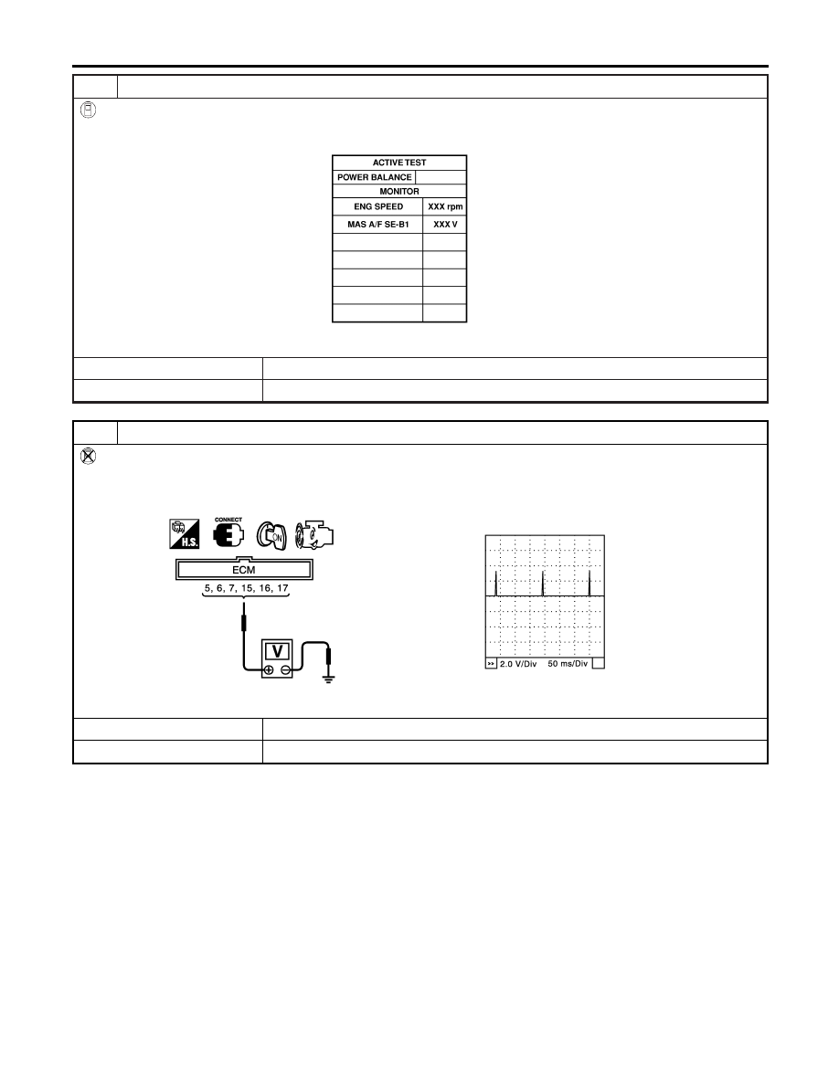
CHECK OVERALL FUNCTION
With CONSULT-II
1. Perform “POWER BALANCE” in “ACTIVE TEST” mode with CONSULT-II.
2. Make sure that all circuits do not produce a momentary engine speed drop.
PBIB0133E
OK or NG
OK
©
INSPECTION END
NG
©
GO TO 14.
3
CHECK OVERALL FUNCTION
Without CONSULT-II
1. Let engine idle.
2. Read the voltage signal between ECM terminals 5, 6, 7, 15, 16, 17 and ground with oscilloscope.
3. Verify that the oscilloscope screen shows the signal wave as shown below.
SEC159D
OK or NG
OK
©
INSPECTION END
NG
©
GO TO 14.
IGNITION SIGNAL
Diagnostic Procedure (Cont’d)
EC-690
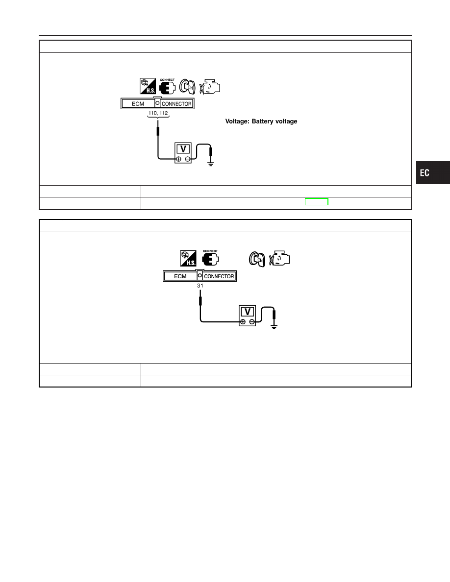
4
CHECK IGNITION COIL POWER SUPPLY CIRCUIT-I
1. Turn ignition switch ON.
2. Check voltage between ECM terminals 110, 112 and ground with CONSULT-II or tester.
SEF366X
OK or NG
OK
©
GO TO 5.
NG
©
Go to TROUBLE DIAGNOSIS FOR POWER SUPPLY, EC-153.
5
CHECK IGNITION COIL POWER SUPPLY CIRCUIT-II
1. Check voltage between ECM terminal 31 and ground with CONSULT-II or tester.
SEC914C
Voltage: Battery voltage
OK or NG
OK
©
GO TO 11.
NG
©
GO TO 6.
GI
MA
EM
LC
FE
AT
AX
SU
BR
ST
RS
BT
HA
SC
EL
IDX
IGNITION SIGNAL
Diagnostic Procedure (Cont’d)
EC-691
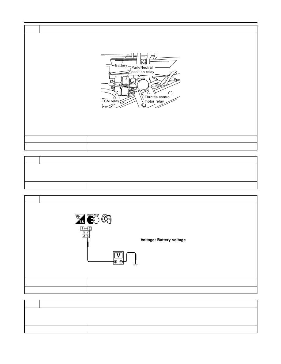
6
CHECK IGNITION COIL POWER SUPPLY CIRCUIT-III
1. Turn ignition switch OFF.
2. Disconnect ECM relay.
3. Disconnect ECM harness connector.
SEC044D
4. Check harness continuity between ECM terminal 31 and ECM relay terminal 7. Refer to Wiring Diagram.
Continuity should exist.
5. Also check harness for short to ground and short to power.
OK or NG
OK
©
GO TO 8.
NG
©
GO TO 7.
7
DETECT MALFUNCTIONING PART
Check the following.
I
Harness connectors E15, F18
I
Harness for open or short between ECM and ECM relay
©
Repair open circuit or short to ground or short to power in harness or connectors.
8
CHECK IGNITION COIL POWER SUPPLY CIRCUIT-IV
Check voltage between ECM relay terminal 6 and ground with CONSULT-II or tester.
SEF368X
OK or NG
OK
©
GO TO 10.
NG
©
GO TO 9.
9
DETECT MALFUNCTIONING PART
Check the following.
I
15A fuse
I
Harness for open and short between ECM relay and fuse
©
Repair or replace harness or connectors.
IGNITION SIGNAL
Diagnostic Procedure (Cont’d)
EC-692
Нет комментариевНе стесняйтесь поделиться с нами вашим ценным мнением.
Текст