Infiniti I35 (A33). Manual — part 335
2
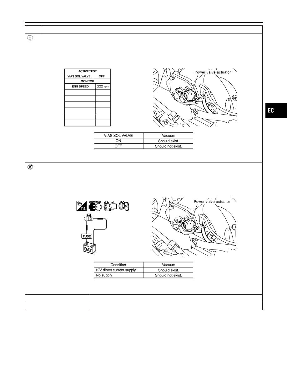
CHECK VACUUM EXISTENCE
With CONSULT-II
1. Stop engine and disconnect vacuum hose connected to power valve actuator.
2. Start engine and let it idle.
3. Perform “VIAS SOL VALVE” in “ACTIVE TEST” mode with CONSULT-II.
4. Turn VIAS control solenoid valve “ON” and “OFF”, and check for the existence of vacuum under the following condi-
tions.
SEC129D
MTBL1174
Without CONSULT-II
1. Stop engine and disconnect vacuum hose connected to power valve actuator.
2. Disconnect VIAS control solenoid valve harness connector.
3. Start engine and let it idle.
4. Apply 12V of direct current between VIAS control solenoid valve terminals 1 and 2.
5. Check for the existence of vacuum under the following conditions.
SEC130D
MTBL1175
OK or NG
OK
©
Repair or replace power valve actuator.
NG
©
GO TO 3.
GI
MA
EM
LC
FE
AT
AX
SU
BR
ST
RS
BT
HA
SC
EL
IDX
VARIABLE INDUCTION AIR CONTROL SYSTEM (VIAS)
Diagnostic Procedure (Cont’d)
EC-681
3
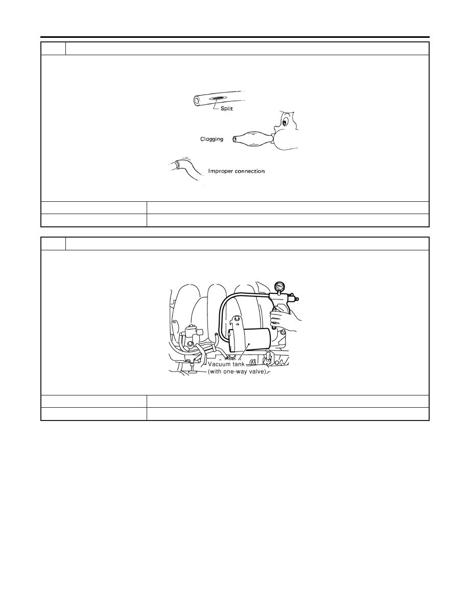
CHECK VACUUM HOSE
1. Stop engine.
2. Check hoses and tubes between intake manifold and power valve actuator for crack, clogging, disconnection or
improper connection.
SEF109L
OK or NG
OK
©
GO TO 4.
NG
©
Replace vacuum hose.
4
CHECK VACUUM TANK
1. Disconnect vacuum hose connected to vacuum tank.
2. Connect a vacuum pump to port (at the center) of vacuum tank.
3. Apply vacuum and make sure that vacuum exists at another port.
SEC131D
OK or NG
OK
©
GO TO 5.
NG
©
Replace vacuum tank.
VARIABLE INDUCTION AIR CONTROL SYSTEM (VIAS)
Diagnostic Procedure (Cont’d)
EC-682
5
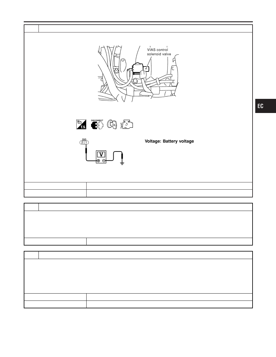
CHECK VIAS CONTROL SOLENOID VALVE POWER SUPPLY CIRCUIT
1. Stop engine.
2. Disconnect VIAS control solenoid valve harness connector.
SEC058D
3. Turn ignition switch ON.
4. Check voltage between terminal 1 and ground with CONSULT-II or tester.
SEF603X
OK or NG
OK
©
GO TO 7.
NG
©
GO TO 6.
6
DETECT MALFUNCTIONING PART
Check the following.
I
Harness connectors M229, F66
I
Fuse block (J/B) connector M19
I
15A fuse
I
Harness continuity between fuse and VIAS control solenoid valve
©
Repair harness or connectors.
7
CHECK VIAS CONTROL SOLENOID VALVE OUTPUT SIGNAL CIRCUIT FOR OPEN AND SHORT
1. Turn ignition switch OFF.
2. Disconnect ECM harness connector.
3. Check harness continuity between ECM terminal 27 and terminal 2. Refer to Wiring Diagram.
Continuity should exist.
4. Also check harness for short to ground and short to power.
OK or NG
OK
©
GO TO 8.
NG
©
Repair open circuit or short to ground or short to power in harness or connectors.
GI
MA
EM
LC
FE
AT
AX
SU
BR
ST
RS
BT
HA
SC
EL
IDX
VARIABLE INDUCTION AIR CONTROL SYSTEM (VIAS)
Diagnostic Procedure (Cont’d)
EC-683
8
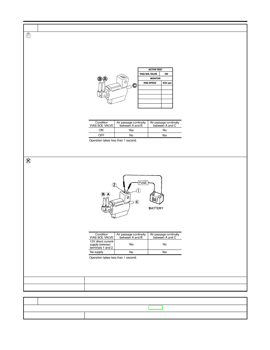
CHECK VIAS CONTROL SOLENOID VALVE
With CONSULT-II
1. Reconnect disconnected harness connector.
2. Turn ignition switch ON.
3. Perform “VIAS SOL VALVE” in “ACTIVE TEST” mode.
4. Check air passage continuity and operation delay time under the following conditions.
PBIB0177E
MTBL1301
Without CONSULT-II
Check air passage continuity and operation delay time under the following conditions.
MEC488B
MTBL1302
OK or NG
OK
©
GO TO 9.
NG
©
Replace VIAS control solenoid valve.
9
CHECK INTERMITTENT INCIDENT
Refer to “TROUBLE DIAGNOSIS FOR INTERMITTENT INCIDENT”, EC-152.
©
INSPECTION END
VARIABLE INDUCTION AIR CONTROL SYSTEM (VIAS)
Diagnostic Procedure (Cont’d)
EC-684
Нет комментариевНе стесняйтесь поделиться с нами вашим ценным мнением.
Текст