Infiniti I35 (A33). Manual — part 467
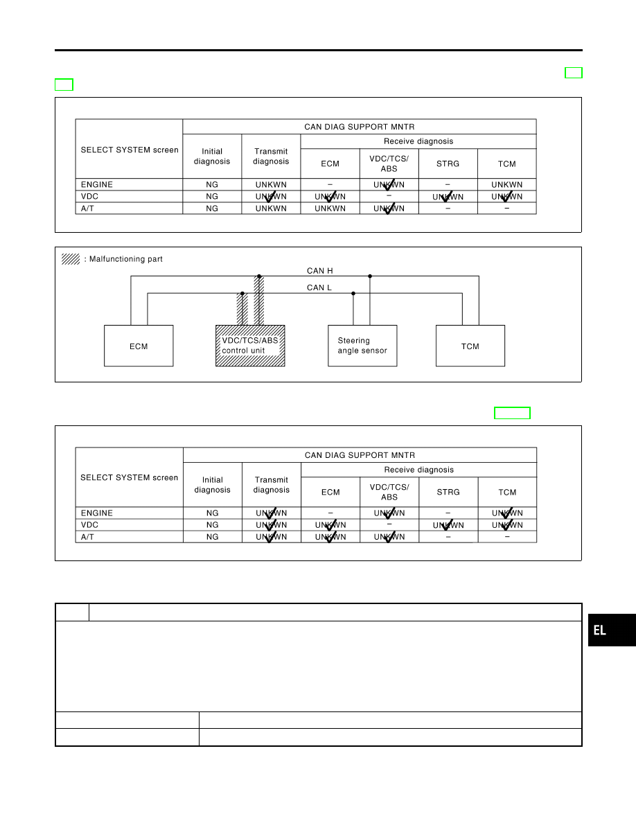
Case 5
=NHEL0331S0305
Check VDC/TCS/ABS control unit circuit. Refer to “VDC/TCS/ABS CONTROL UNIT CIRCUIT CHECK” (EL-
472).
PKIA8333E
PKIA8342E
Case 6
NHEL0331S0306
Check CAN communication circuit. Refer to “CAN COMMUNICATION CIRCUIT CHECK” (EL-473).
PKIA8334E
CIRCUIT CHECK BETWEEN VDC/TCS/ABS CONTROL UNIT AND STEERING ANGLE
SENSOR
NHEL0331S09
1
CHECK CONNECTOR
1. Turn ignition switch OFF.
2. Check following terminals and connector for damage, bend and loose connection. (control unit side, sensor side and
harness side)
I
VDC/TCS/ABS control unit
I
Steering angle sensor
I
Between VDC/TCS/ABS control unit and steering angle sensor
OK or NG
OK
©
GO TO 2.
NG
©
Repair terminal or connector.
GI
MA
EM
LC
EC
FE
AT
AX
SU
BR
ST
RS
BT
HA
SC
IDX
CAN SYSTEM (FOR VDC MODELS)
Trouble Diagnoses (Cont’d)
EL-469
2
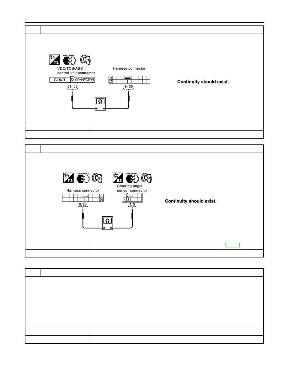
CHECK HARNESS FOR OPEN CIRCUIT
1. Disconnect VDC/TCS/ABS control unit connector and harness connector B58.
2. Check continuity between VDC/TCS/ABS control unit harness connector B57 terminals 61 (L), 63 (R) and harness con-
nector B58 terminals 9 (L), 20 (R).
SEL563Y
OK or NG
OK
©
GO TO 3.
NG
©
Repair harness.
3
CHECK HARNESS FOR OPEN CIRCUIT
1. Disconnect steering angle sensor connector M218.
2. Check continuity between harness connector M227 terminals 9 (L), 20 (R) and steering angle sensor harness connec-
tor M218 terminals 4 (L), 5 (R).
SEL834Y
OK or NG
OK
©
Connect all the connectors and diagnose again. Refer to “Work Flow” (EL-465).
NG
©
Repair harness.
ECM CIRCUIT CHECK
NHEL0331S05
1
CHECK CONNECTOR
1. Turn ignition switch OFF.
2. Check following terminals and connector for damage, bend and loose connection. (control module side and harness
side)
I
ECM
I
Harness connector F53
I
Harness connector M223
I
Harness connector M2
I
Harness connector B2
OK or NG
OK
©
GO TO 2.
NG
©
Repair terminal or connector.
CAN SYSTEM (FOR VDC MODELS)
Trouble Diagnoses (Cont’d)
EL-470
2
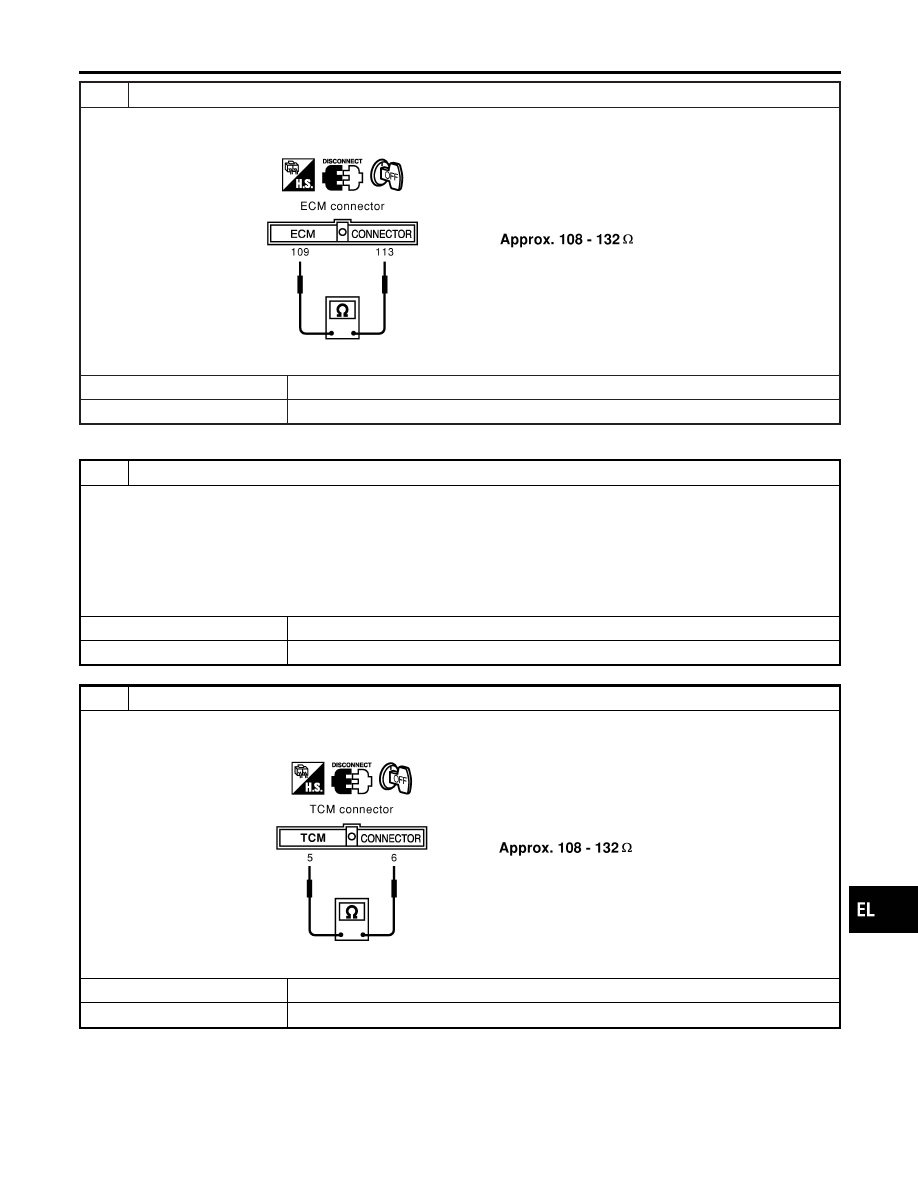
CHECK HARNESS FOR OPEN CIRCUIT
1. Disconnect ECM connector.
2. Check resistance between ECM harness connector F48 terminals 109 (L) and 113 (R).
SEL437Y
OK or NG
OK
©
Replace ECM.
NG
©
Repair harness between VDC/TCS/ABS control unit and ECM.
TCM CIRCUIT CHECK
NHEL0331S10
1
CHECK CONNECTOR
1. Turn ignition switch OFF.
2. Check following terminals and connector for damage, bend and loose connection. (control module side and harness
side)
I
TCM
I
Harness connector F53
I
Harness connector M223
OK or NG
OK
©
GO TO 2.
NG
©
Repair terminal or connector.
2
CHECK HARNESS FOR OPEN CIRCUIT
1. Disconnect TCM connector.
2. Check resistance between TCM harness connector F51 terminals 5 (L) and 6 (R).
SEL439Y
OK or NG
OK
©
Replace TCM.
NG
©
Repair harness between steering angle sensor and TCM.
GI
MA
EM
LC
EC
FE
AT
AX
SU
BR
ST
RS
BT
HA
SC
IDX
CAN SYSTEM (FOR VDC MODELS)
Trouble Diagnoses (Cont’d)
EL-471
STEERING ANGLE SENSOR CIRCUIT CHECK
NHEL0331S11
1
CHECK CONNECTOR
1. Turn ignition switch OFF.
2. Check the terminals and connector of steering angle sensor for damage, bend and loose connection. (sensor side and
harness side)
OK or NG
OK
©
GO TO 2.
NG
©
Repair terminal or connector.
2
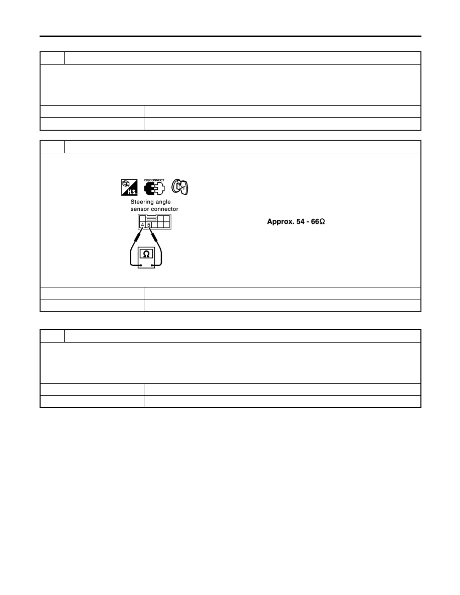
CHECK HARNESS FOR OPEN CIRCUIT
1. Disconnect steering angle sensor connector.
2. Check resistance between steering angle sensor harness connector M218 terminals 4 (L) and 5 (R).
SEL565YA
OK or NG
OK
©
Replace steering angle sensor.
NG
©
Repair harness between steering angle sensor and harness connector M227.
VDC/TCS/ABS CONTROL UNIT CIRCUIT CHECK
NHEL0331S06
1
CHECK CONNECTOR
1. Turn ignition switch OFF.
2. Check the terminals and connector of VDC/TCS/ABS control unit for damage, bend and loose connection. (control unit
side and harness side)
OK or NG
OK
©
GO TO 2.
NG
©
Repair terminal or connector.
CAN SYSTEM (FOR VDC MODELS)
Trouble Diagnoses (Cont’d)
EL-472
Нет комментариевНе стесняйтесь поделиться с нами вашим ценным мнением.
Текст