Infiniti I35 (A33). Manual — part 465
9
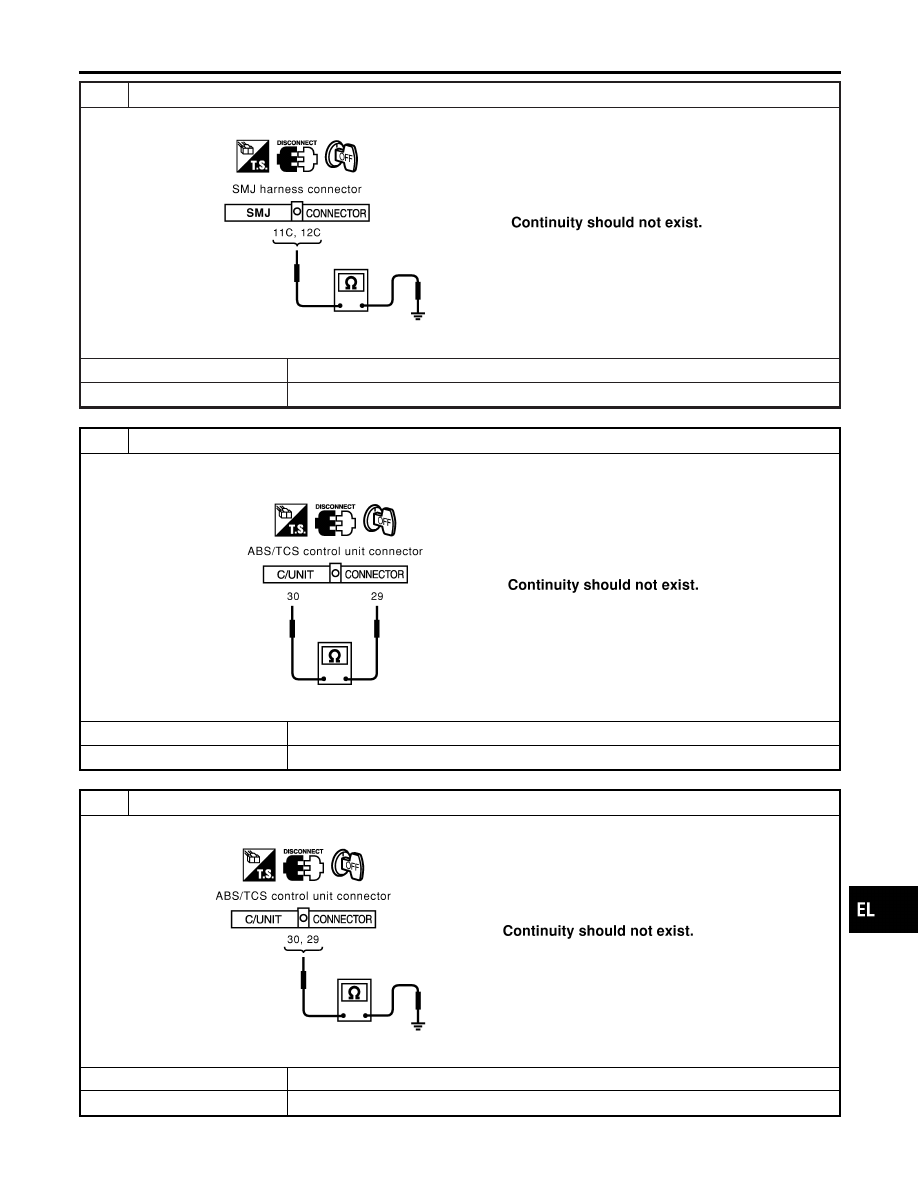
CHECK HARNESS FOR SHORT CIRCUIT
Check continuity between harness connector M15 terminals 11C (L), 12C (R) and ground.
SEL445Y
OK or NG
OK
©
GO TO 10.
NG
©
Repair harness between harness connector M223 and harness connector M15.
10
CHECK HARNESS FOR SHORT CIRCUIT
1. Disconnect ABS/TCS control unit connector.
2. Check continuity between ABS/TCS control unit harness connector E162 terminals 30 (L) and 29 (R).
SEL446Y
OK or NG
OK
©
GO TO 11.
NG
©
Repair harness between ABS/TCS control unit and harness connector E81.
11
CHECK HARNESS FOR SHORT CIRCUIT
Check continuity between ABS/TCS control unit harness connector E162 terminals 30 (L), 29 (R) and ground.
SEL447Y
OK or NG
OK
©
GO TO 12.
NG
©
Repair harness between ABS/TCS control unit and harness connector E81.
GI
MA
EM
LC
EC
FE
AT
AX
SU
BR
ST
RS
BT
HA
SC
IDX
CAN SYSTEM (FOR TCS MODELS)
Trouble Diagnoses (Cont’d)
EL-461
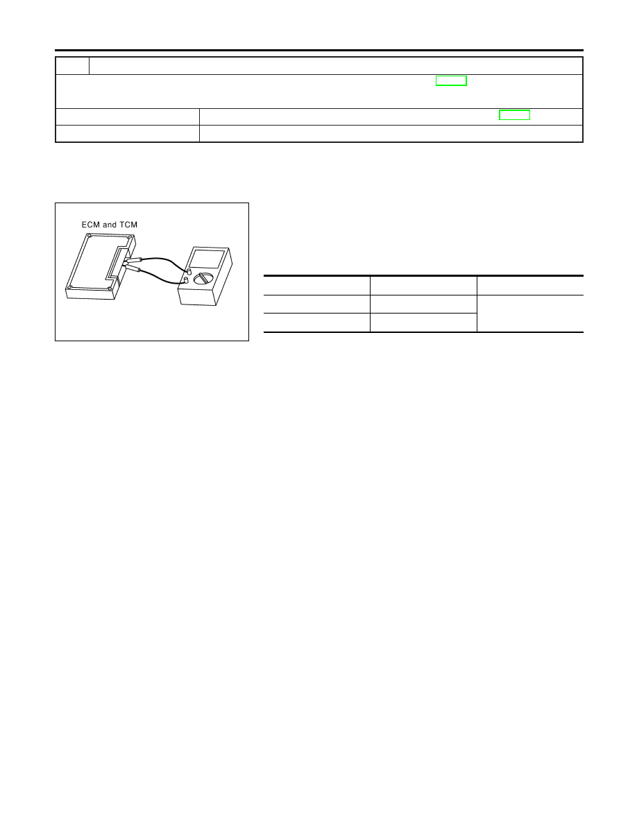
12
ECM/TCM INTERNAL CIRCUIT INSPECTION
Check components inspection. Refer to “ECM/TCM INTERNAL CIRCUIT INSPECTION” (EL-462).
OK or NG
OK
©
Connect all the connectors and diagnose again. Refer to “Work Flow” (EL-452).
NG
©
Replace ECM and/or TCM.
SEL433Y
Component Inspection
NHEL0327
ECM/TCM INTERNAL CIRCUIT INSPECTION
NHEL0327S01
I
Remove ECM and TCM from vehicle.
I
Check resistance between ECM terminals 109 and 113.
I
Check resistance between TCM terminals 5 and 6.
Unit
Terminal
Resistance value (
Ω
)
ECM
109 - 113
Approx. 108 - 132
TCM
5 - 6
CAN SYSTEM (FOR TCS MODELS)
Trouble Diagnoses (Cont’d)
EL-462
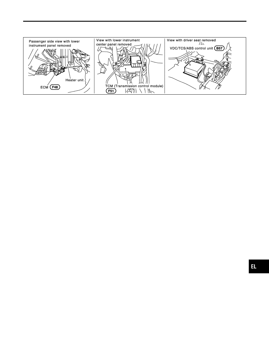
Component Parts and Harness Connector
Location
NHEL0328
SEL573Y
System Description
NHEL0329
CAN (Controller Area Network) is a serial communication line for real time application. It is an on-vehicle mul-
tiplex communication line with high data communication speed and excellent error detection ability. Many
electronic control units are equipped onto a vehicle, and each control unit shares information and links with
other control units during operation (not independent). In CAN communication, control units are connected with
2 communication lines (CAN H line, CAN L line) allowing a high rate of information transmission with less wir-
ing. Each control unit transmits/receives data but selectively reads required data only.
GI
MA
EM
LC
EC
FE
AT
AX
SU
BR
ST
RS
BT
HA
SC
IDX
CAN SYSTEM (FOR VDC MODELS)
Component Parts and Harness Connector Location
EL-463
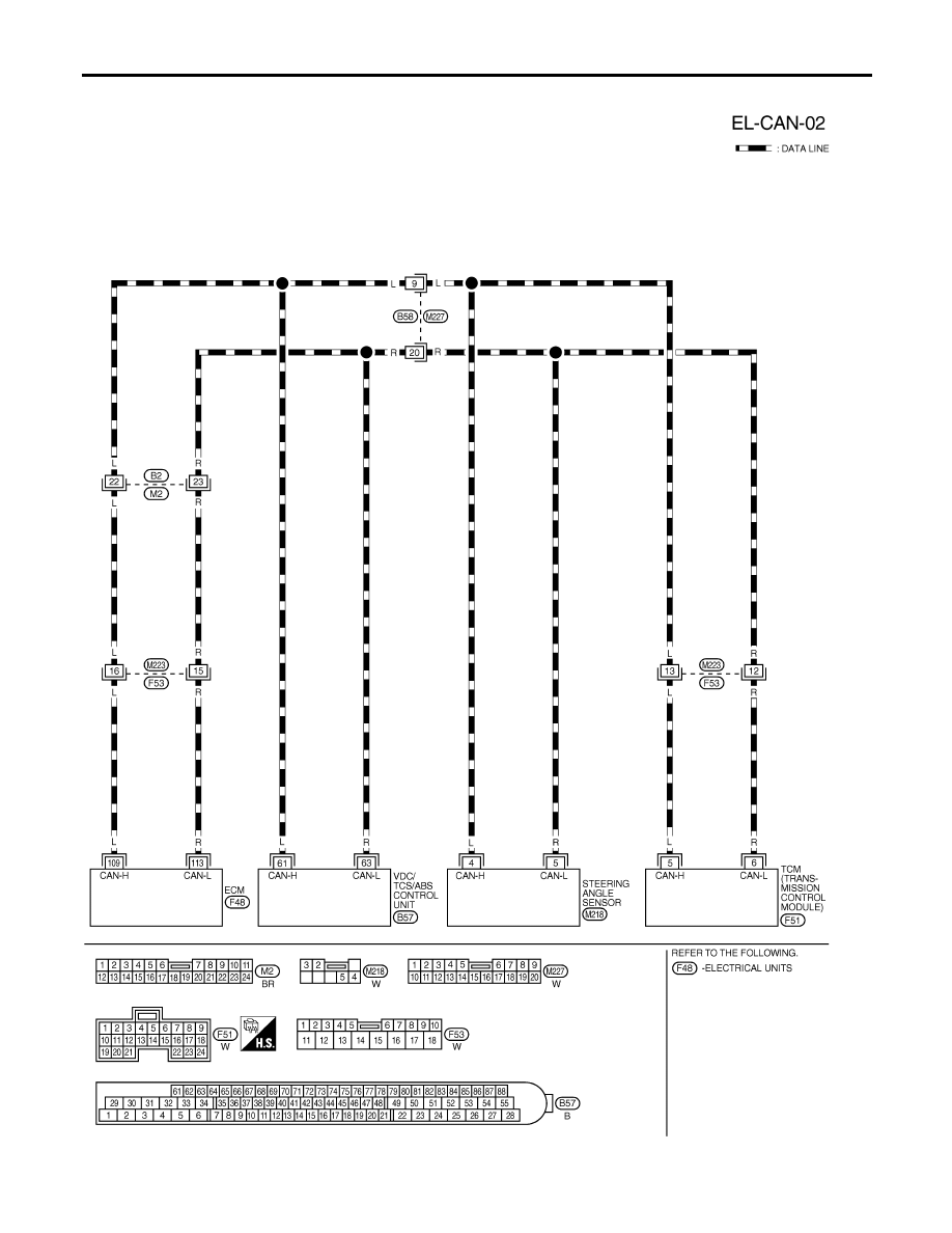
Wiring Diagram — CAN —
NHEL0330
MEL647Q
CAN SYSTEM (FOR VDC MODELS)
Wiring Diagram — CAN —
EL-464
Нет комментариевНе стесняйтесь поделиться с нами вашим ценным мнением.
Текст