Infiniti I35 (A33). Manual — part 90
AAT882
7.
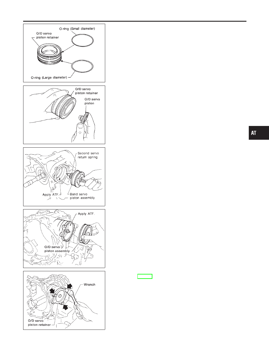
Install O-rings to O/D servo piston retainer.
I
Apply ATF to O-rings.
I
Pay attention to position of each O-ring.
AAT886
8.
Install O/D servo piston to O/D servo piston retainer.
SAT865H
9.
Install band servo piston assembly and 2nd servo return spring
to transmission case.
I
Apply ATF to O-ring of band servo piston and transmis-
sion case.
AAT885
10. Install O/D servo piston assembly to transmission case.
I
Apply ATF to O-ring of band servo piston and transmis-
sion case.
AAT879
11. Install O/D servo piston retainer to transmission case.
Refer to AT-353.
GI
MA
EM
LC
EC
FE
AX
SU
BR
ST
RS
BT
HA
SC
EL
IDX
REPAIR FOR COMPONENT PARTS
Band Servo Piston Assembly (Cont’d)
AT-357
Final Drive
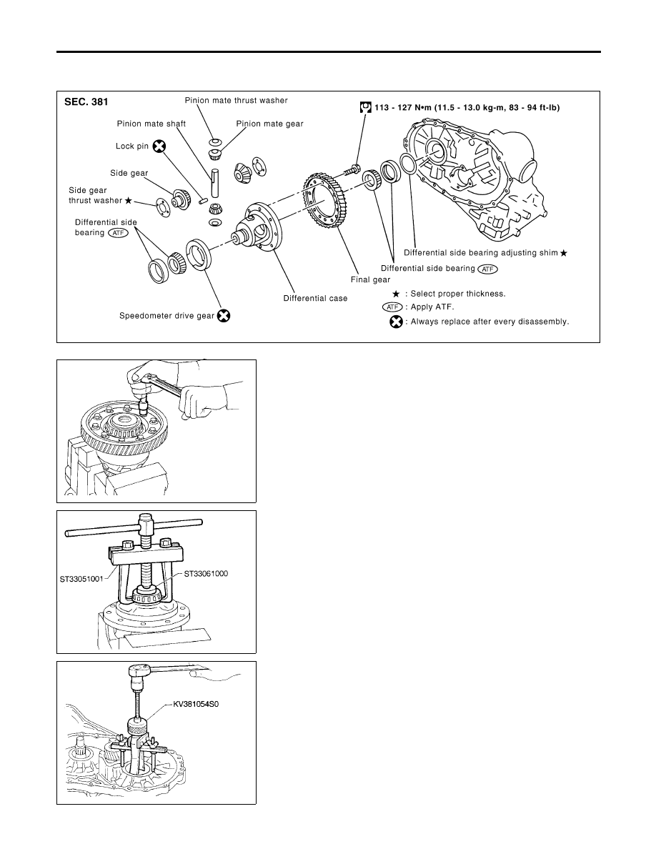
COMPONENTS
NHAT0173
SAT849K
SMT505B
DISASSEMBLY
NHAT0174
1.
Remove final gear.
SMT744AA
2.
Press out differential side bearings.
I
Be careful not to mix up the right and left bearings.
SAT010FA
3.
Remove differential side bearing outer race, and side bearing
adjusting shim from transmission case.
REPAIR FOR COMPONENT PARTS
Final Drive
AT-358
SAT313D
4.
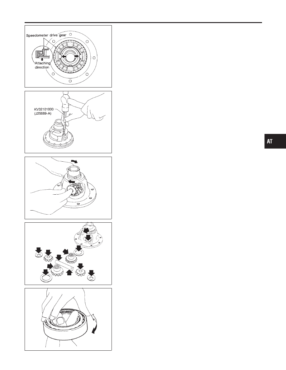
Remove speedometer drive gear.
SAT904D
5.
Drive out pinion mate shaft lock pin.
SAT316D
6.
Draw out pinion mate shaft lock pin.
7.
Remove pinion mate gears and side gears.
SAT544F
INSPECTION
NHAT0175
Gear, washer, shaft and case
NHAT0175S01
I
Check mating surfaces of differential case, side gears and
pinion mate gears.
I
Check washers for wear.
SPD715
Bearings
NHAT0175S03
I
Make sure bearings roll freely and are free from noise, cracks,
pitting or wear.
I
When replacing taper roller bearing, replace outer and
inner race as a set.
GI
MA
EM
LC
EC
FE
AX
SU
BR
ST
RS
BT
HA
SC
EL
IDX
REPAIR FOR COMPONENT PARTS
Final Drive (Cont’d)
AT-359
SMT839
ASSEMBLY
NHAT0176
1.
Attach side gear thrust washers to side gears, then install pin-
ion mate thrust washers and pinion mate gears in place.
SMT087A
2.
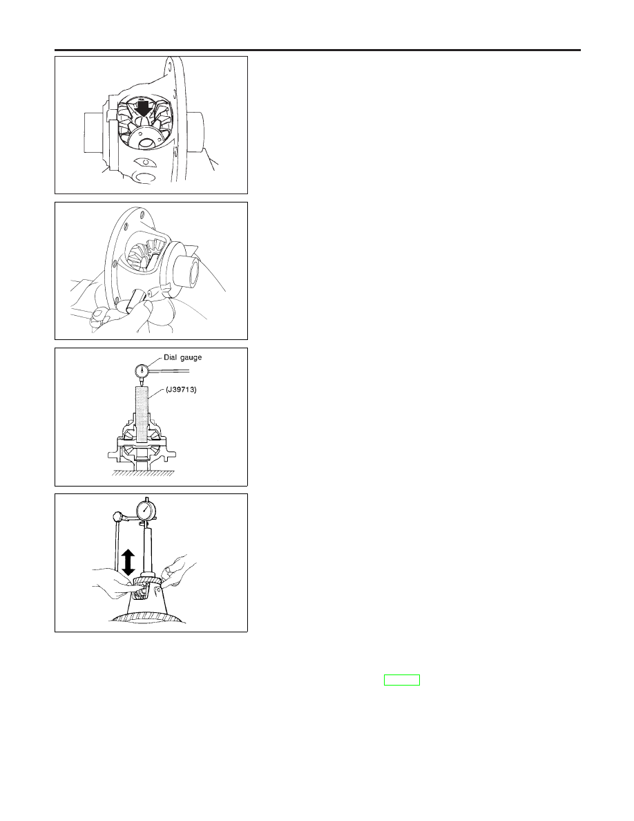
Insert pinion mate shaft.
I
When inserting, be careful not to damage pinion mate
thrust washers.
AAT782
3.
Measure clearance between side gear and differential case
with washers following the procedure below:
a.
Set Tool and dial indicator on side gear.
SMT611A
b.
Move side gear up and down to measure dial indicator deflec-
tion. Always measure indicator deflection on both side gears.
Clearance between side gear and differential case with
washers:
0.1 - 0.2 mm (0.004 - 0.008 in)
c.
If not within specification, adjust clearance by changing thick-
ness of side gear thrust washers.
Side gear thrust washer:
Refer to SDS, AT-385.
REPAIR FOR COMPONENT PARTS
Final Drive (Cont’d)
AT-360
Нет комментариевНе стесняйтесь поделиться с нами вашим ценным мнением.
Текст