Infiniti I35 (A33). Manual — part 240
5
CHECK THROTTLE POSITION SENSOR 1 INPUT SIGNAL CIRCUIT FOR OPEN AND SHORT
1. Check harness continuity between ECM terminal 83 and electric throttle control actuator terminal 4.
Refer to Wiring Diagram.
Continuity should exist.
2. Also check harness for short to ground and short to power.
OK or NG
OK
©
GO TO 6.
NG
©
Repair open circuit or short to ground or short to power in harness or connectors.
6
CHECK THROTTLE POSITION SENSOR
Refer to “Component Inspection”, EC-301.
OK or NG
OK
©
GO TO 8.
NG
©
GO TO 7.
7
REPLACE ELECTRIC THROTTLE CONTROL ACTUATOR
1. Replace the electric throttle control actuator.
2. Perform “Throttle Valve Closed Position Learning”, EC-70.
3. Perform “Idle Air Volume Learning”, EC-70.
©
INSPECTION END
8
CHECK INTERMITTENT INCIDENT
Refer to “TROUBLE DIAGNOSIS FOR INTERMITTENT INCIDENT”, EC-152.
©
INSPECTION END
SEC900C
Component Inspection
NHEC1378
THROTTLE POSITION SENSOR
1.
Reconnect all harness connectors disconnected.
2.
Perform “Throttle Valve Closed Position Learning”, EC-70.
3.
Turn ignition switch ON.
4.
Set selector lever to D position.
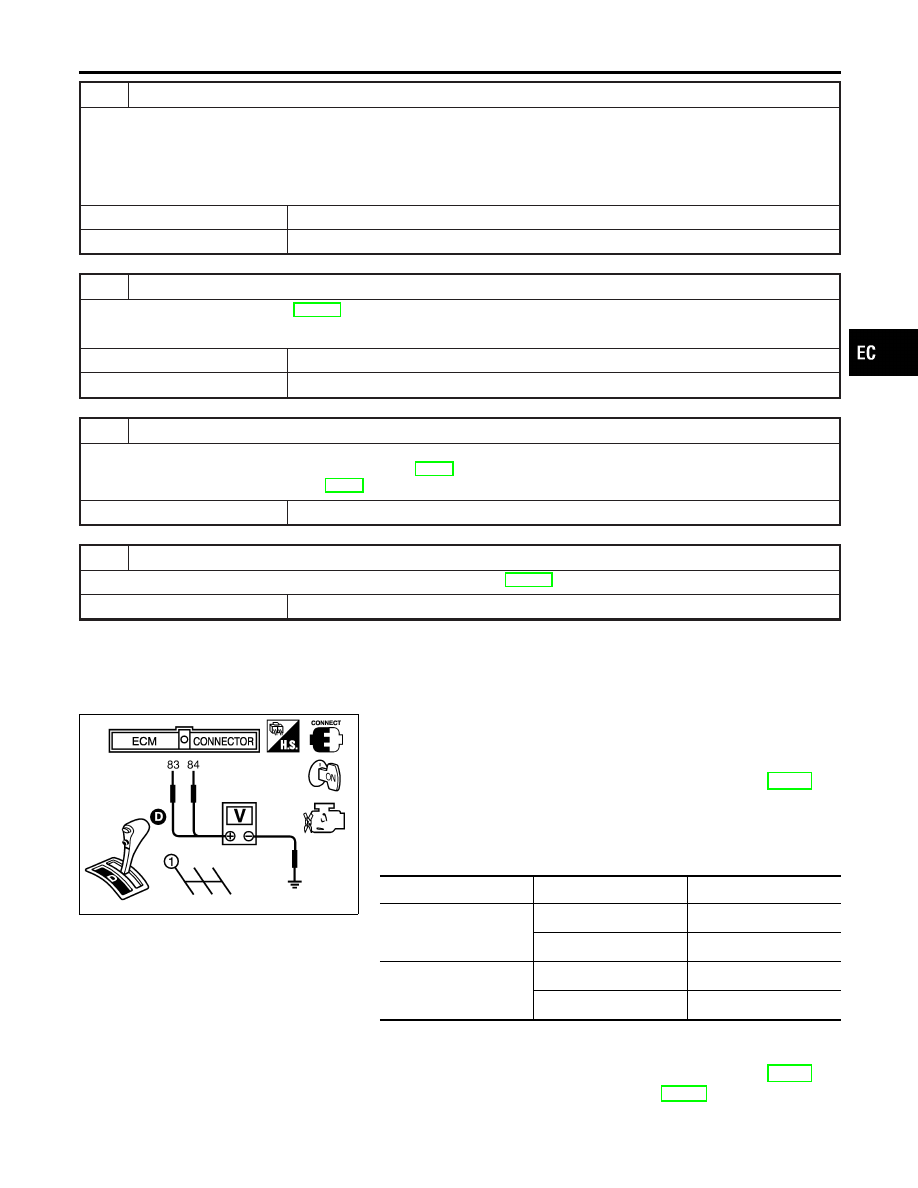
5.
Check voltage between ECM terminals 83 (TP sensor 1), 84
(TP sensor 2) and ground under the following conditions.
Terminal
Accelerator pedal
Voltage
83
(Throttle position sensor
1)
Fully released
More than 0.36V
Fully depressed
Less than 4.75V
84
(Throttle position sensor
2)
Fully released
Less than 4.75V
Fully depressed
More than 0.36V
6.
If NG, replace electric throttle control actuator and go to the
next step.
7.
Perform “Throttle Valve Closed Position Learning”, EC-70.
8.
Perform “Idle Air Volume Learning”, EC-70.
GI
MA
EM
LC
FE
AT
AX
SU
BR
ST
RS
BT
HA
SC
EL
IDX
DTC P0222, P0223 TP SENSOR
Diagnostic Procedure (Cont’d)
EC-301

On Board Diagnosis Logic
NHEC0929
When a misfire occurs, engine speed will fluctuate. If the engine
speed fluctuates enough to cause the CKP sensor signal to vary,
ECM can determine that a misfire is occurring.
Sensor
Input Signal to ECM
ECM function
Crankshaft position sensor (POS)
Engine speed
On board diagnosis of misfire
The misfire detection logic consists of the following two conditions.
1.
One Trip Detection Logic (Three Way Catalyst Damage)
On the first trip that a misfire condition occurs that can dam-
age the three way catalyst (TWC) due to overheating, the MIL
will blink.
When a misfire condition occurs, the ECM monitors the CKP
sensor signal every 200 engine revolutions for a change.
When the misfire condition decreases to a level that will not
damage the TWC, the MIL will turn off.
If another misfire condition occurs that can damage the TWC
on a second trip, the MIL will blink.
When the misfire condition decreases to a level that will not
damage the TWC, the MIL will remain on.
If another misfire condition occurs that can damage the TWC,
the MIL will begin to blink again.
2.
Two Trip Detection Logic (Exhaust quality deterioration)
For misfire conditions that will not damage the TWC (but will
affect vehicle emissions), the MIL will only light when the mis-
fire is detected on a second trip. During this condition, the ECM
monitors the CKP sensor signal every 1,000 engine revolu-
tions.
A misfire malfunction can be detected on any one cylinder or
on multiple cylinders.
DTC No.
Trouble diagnosis
name
DTC Detecting Condition
Possible Cause
P0300
0300
Multiple cylinder mis-
fire detected
Multiple cylinders misfire, No. 1 cylinder misfires,
No. 2 cylinder misfires, No. 3 cylinder misfires, No.
4 cylinder misfires, No. 5 cylinder misfires and No.
6 cylinder misfires.
I
Improper spark plug
I
Insufficient compression
I
Incorrect fuel pressure
I
The injector circuit is open or shorted
I
Injectors
I
Intake air leak
I
The ignition secondary circuit is open
or shorted
I
Lack of fuel
I
Drive plate
I
Heated oxygen sensor 1
I
Incorrect PCV hose connection
P0301
0301
No. 1 cylinder misfire
detected
P0302
0302
No. 2 cylinder misfire
detected
P0303
0303
No. 3 cylinder misfire
detected
P0304
0304
No. 4 cylinder misfire
detected
P0305
0305
No. 5 cylinder misfire
detected
P0306
0306
No. 6 cylinder misfire
detected
DTC P0300 - P0306 MULTIPLE CYLINDER MISFIRE, NO. 1 - 6 CYLINDER
MISFIRE
On Board Diagnosis Logic
EC-302
SEF213Y
DTC Confirmation Procedure
NHEC0930
CAUTION:
Always drive vehicle at a safe speed.
NOTE:
If DTC Confirmation Procedure has been previously conducted,
always turn ignition switch OFF and wait at least 10 seconds before
conducting the next test.
WITH CONSULT-II
NHEC0930S01
1)
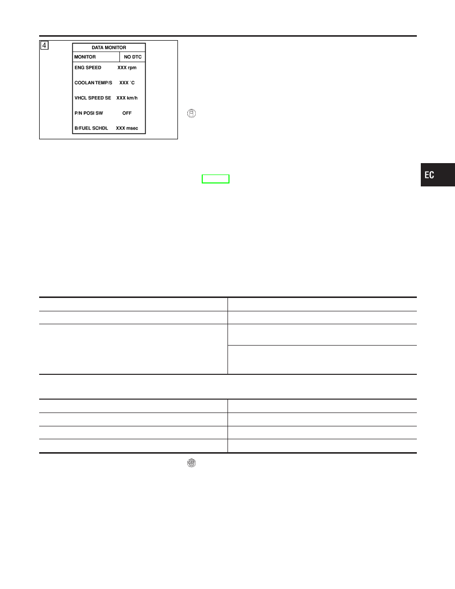
Turn ignition switch ON, and select “DATA MONITOR” mode
with CONSULT-II.
2)
Start engine and warm it up to normal operating temperature.
3)
Turn ignition switch OFF and wait at least 10 seconds.
4)
Restart engine and let it idle for about 15 minutes.
5)
If 1st trip DTC is detected, go to “Diagnostic Procedure”,
EC-304.
NOTE:
If 1st trip DTC is not detected during above procedure, performing
the following procedure is advised.
1)
Turn ignition switch OFF and wait at least 10 seconds.
2)
Start engine and drive the vehicle under the similar conditions
to (1st trip) Freeze Frame Data for a certain time. Refer to the
table below.
Hold the accelerator pedal as steady as possible.
The similar conditions to (1st trip) Freeze Frame Data means the
vehicle operation that the following conditions should be satisfied
at the same time.
Engine speed
Engine speed in the freeze frame data
±
400 rpm
Vehicle speed
Vehicle speed in the freeze frame data
±
10 km/h (5 MPH)
Engine coolant temperature (T) condition
When the freeze frame data shows lower than 70°C (158°F),
T should be lower than 70°C (158°F).
When the freeze frame data shows higher than or equal to
70°C (158°F),
T should be higher than or equal to 70°C (158°F).
The time to driving varies according to the engine speed in the
freeze frame data.
Engine speed
Time
Around 1,000 rpm
Approximately 10 minutes
Around 2,000 rpm
Approximately 5 minutes
More than 3,000 rpm
Approximately 3.5 minutes
WITH GST
NHEC0930S02
Follow the procedure “With CONSULT-II” above.
GI
MA
EM
LC
FE
AT
AX
SU
BR
ST
RS
BT
HA
SC
EL
IDX
DTC P0300 - P0306 MULTIPLE CYLINDER MISFIRE, NO. 1 - 6 CYLINDER
MISFIRE
DTC Confirmation Procedure
EC-303
Diagnostic Procedure
NHEC0931
1
CHECK FOR INTAKE AIR LEAK
1. Start engine and run it at idle speed.
2. Listen for the sound of the intake air leak.
3. Check PCV hose connection.
OK or NG
OK
©
GO TO 2.
NG
©
Discover air leak location and repair.
2
CHECK FOR EXHAUST SYSTEM CLOGGING
1. Stop engine and visually check exhaust tube, three way catalyst and muffler for dents.
OK or NG
OK
©
GO TO 3.
NG
©
Repair or replace it.
3
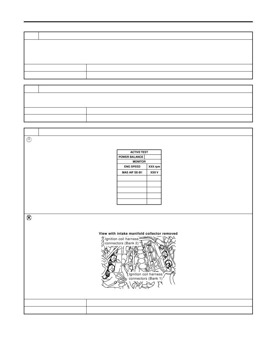
PERFORM POWER BALANCE TEST
With CONSULT-II
1. Perform “POWER BALANCE” in “ACTIVE TEST” mode.
SEC136D
2. Is there any cylinder which does not produce a momentary engine speed drop?
Without CONSULT-II
When disconnecting each ignition coil harness connector one at a time, is there any cylinder which does not produce a
momentary engine speed drop?
SEC120D
Yes or No
Yes
©
GO TO 5.
No
©
GO TO 4.
DTC P0300 - P0306 MULTIPLE CYLINDER MISFIRE, NO. 1 - 6 CYLINDER
MISFIRE
Diagnostic Procedure
EC-304
Нет комментариевНе стесняйтесь поделиться с нами вашим ценным мнением.
Текст