Infiniti G37 Coupe. Manual — part 628
CAMSHAFT
EM-87
< DISASSEMBLY AND ASSEMBLY >
C
D
E
F
G
H
I
J
K
L
M
A
EM
N
P
O
2.
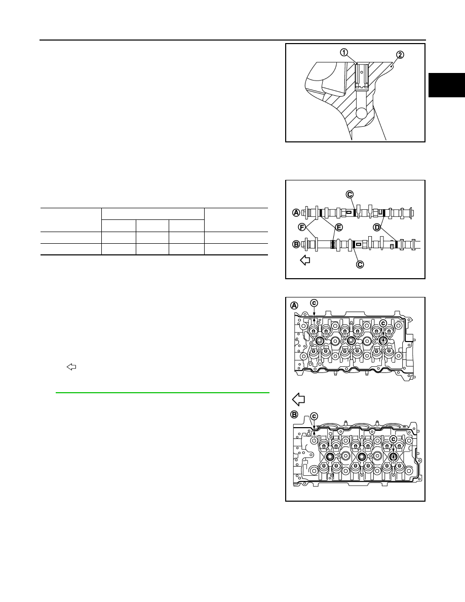
Install oil filter (1), if removed.
• Do not project from the cylinder head (2) surface.
3.
Install valve lifter.
• Install it in the original position.
4.
Install camshaft (EXH).
• Distinction between camshaft (EXH) (bank 1 and bank 2) is
performed with the identification mark.
5.
Install VVEL ladder assembly as follows:
a.
Apply a continuous bead of liquid gasket with tube presser
(commercial service tool) to the cylinder head as shown in the
figure.
Use Genuine RTV Silicone Sealant or equivalent. Refer to
GI-15, "Recommended Chemical Products and Sealants"
.
JPBIA1390ZZ
Bank
Paint marks
Identification mark
(F)
M1 (C)
M2 (D)
M3 (E)
Bank 1 (A)
No
Blue
Light blue
1N
Bank 2 (B)
No
Blue
Light blue
1P
JPBIA1129ZZ
A
: Bank 1
B
: Bank 2
c
: 3.4 - 4.4 mm (0.134 - 0.173 in) dia
: Engine front
JPBIA1123ZZ
EM-88
< DISASSEMBLY AND ASSEMBLY >
CAMSHAFT
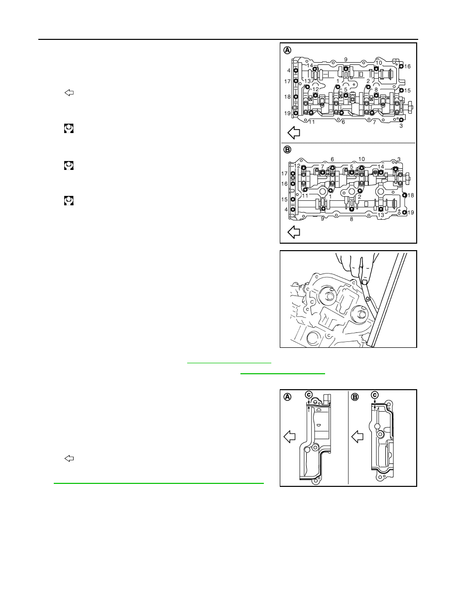
b.
Tighten mounting bolts in the following step, in numerical order
as shown.
i.
Tighten bolts in numerical order as shown.
ii.
Tighten bolts in numerical order as shown.
iii.
Tighten bolts in numerical order as shown.
6.
Measure difference in levels between front end faces of VVEL
ladder assembly and cylinder head.
• Measure two positions (both intake and exhaust side) for a
single bank.
• If the measured value is out of the standard, re-install VVEL
ladder assembly.
7.
Install rear timing chain case. Refer to
.
8.
Install camshaft sprockets and timing chains. Refer to
.
9.
Install actuator bracket (rear) as follows:
a.
Apply a continuous bead of liquid gasket with tube presser
(commercial service tool) to the actuator bracket (rear) as
shown in the figure.
Use Genuine RTV Silicone Sealant or equivalent. Refer to
GI-15, "Recommended Chemical Products and Sealants"
.
CAUTION:
Never apply gasket to the oil passage.
A
: Bank 1
B
: Bank 2
: Engine front
: 1.96 N·m (0.20 kg-m, 1 ft-lb)
: 5.88 N·m (0.60 kg-m, 4 ft-lb)
: 10.4 N·m (1.1 kg-m, 8 ft-lb)
JPBIA1103ZZ
Standard
:
−
0.14 to 0.14 mm (
−
0.0055 to 0.0055 in)
EMQ0044D
A
: Bank 1
B
: Bank 2
c
: 3.4 - 4.4 mm (0.134 - 0.173 in) dia
: Engine front
JPBIA1130ZZ
CAMSHAFT
EM-89
< DISASSEMBLY AND ASSEMBLY >
C
D
E
F
G
H
I
J
K
L
M
A
EM
N
P
O
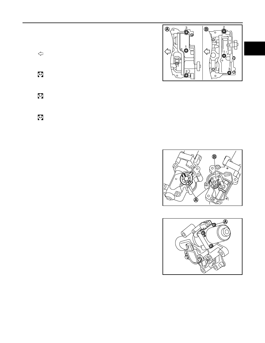
b.
Tighten mounting bolts in the following steps, in numerical order
as shown.
i.
Tighten bolts in numerical order as shown.
ii.
Tighten bolts in numerical order as shown.
iii.
Tighten bolts in numerical order as shown.
10. Install new VVEL actuator sub assembly as follows:
CAUTION:
Regarding replacement, because VVEL actuator sub assembly and VVEL control shaft position
sensor are controlled on a one-on-one basis, replace them as a set.
NOTE:
• VVEL actuator arm (B) is factory-fixed at 5.5 degrees from the
small lift with a holding jig (A).
• The holding jig is supplied in the new VVEL actuator sub
assembly.
CAUTION:
• Never disassemble VVEL actuator sub assembly. [Never
loosen actuator motor mounting bolts (A) shown in the
figure]
• Never shock VVEL actuator sub assembly.
A
: Bank 1
B
: Bank 2
: Engine front
: 1.96 N·m (0.20 kg-m, 1 ft-lb)
: 5.88 N·m (0.60 kg-m, 4 ft-lb)
: 31.4 N·m (3.2 kg-m, 23 ft-lb)
JPBIA1131ZZ
JPBIA1137ZZ
JPBIA1120ZZ
EM-90
< DISASSEMBLY AND ASSEMBLY >
CAMSHAFT
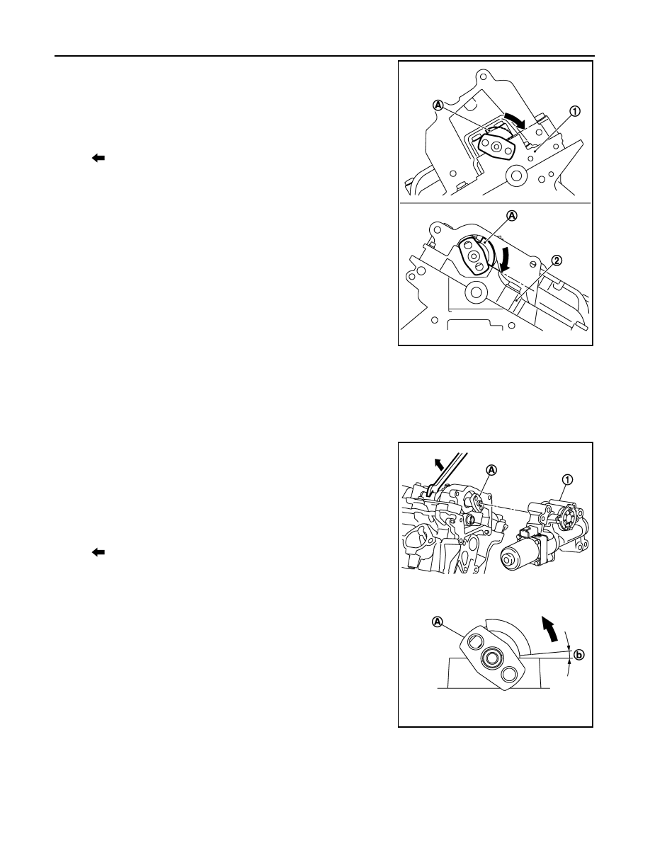
a.
Move control shaft to the position of small lift stopper.
• The position where a part of the stopper of control shaft con-
tacts VVEL ladder bracket.
CAUTION:
Be careful not to damage the stopper surface.
• If control shaft cannot be moved, set crankshaft in position referring to the information below. (To dis-
place cam nose)
b.
Hold two flat areas of control shaft with a wrench, and rotate the
control shaft (5.5 degrees from the stopper) to the large lift side.
(This is for aligning the bolt hole of control shaft and the hole of
VVEL actuator arm.)
1
: VVEL ladder assembly (bank 2)
2
: VVEL ladder assembly (bank 1)
A
: Stopper of control shaft
: Small lift side
JPBIA1122ZZ
Bank 1
: Turn 120 degrees from No. 1 cylinder at TDC
Bank 2
: No. 1 cylinder at TDC
1
: VVEL actuator sub assembly (bank 1)
A
: Control shaft
b
: 5.5 degrees
: Large lift side
JPBIA1132ZZ
Нет комментариевНе стесняйтесь поделиться с нами вашим ценным мнением.
Текст