Infiniti G37 Coupe. Manual — part 626
REAR TIMING CHAIN CASE
EM-79
< DISASSEMBLY AND ASSEMBLY >
C
D
E
F
G
H
I
J
K
L
M
A
EM
N
P
O
Disassembly and Assembly
INFOID:0000000001547553
DISASSEMBLY
1.
Remove front timing chain case and timing chain. Refer to
EM-49, "Removal and Installation"
.
2.
Remove water pump. Refer to
.
3.
Remove oil pan (upper). Refer to
.
4.
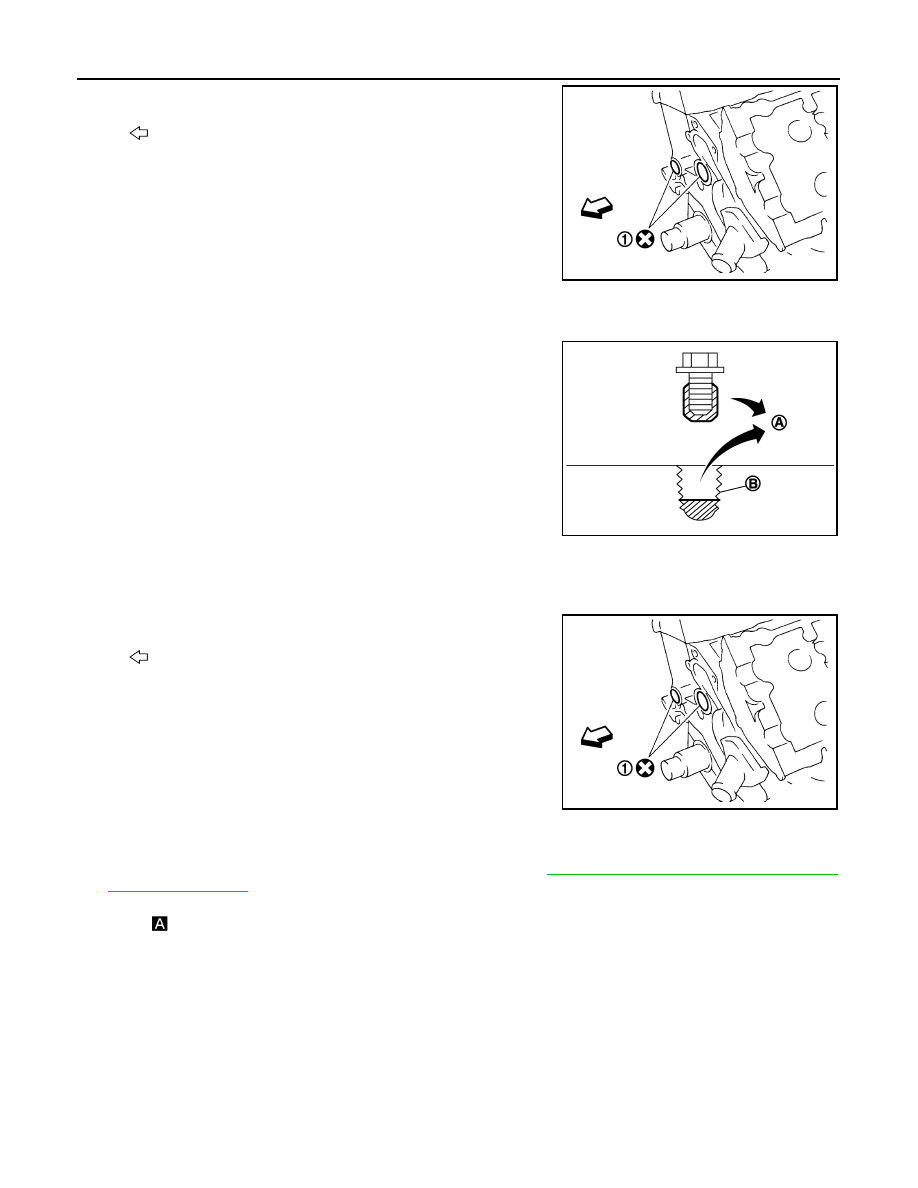
Remove rear timing chain case as follows:
a.
Loosen mounting bolts in reverse order as shown in the figure.
b.
Cut liquid gasket using the seal cutter [SST: KV10111100
(J37228)] and remove rear timing chain case.
CAUTION:
• Never remove plate metal cover (1) of oil passage.
• After removal, handle rear timing chain case carefully so
it does not tilt, cant, or warp under a load.
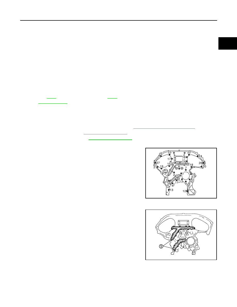
10.
Slack guide
11. Crankshaft sprocket
12.
Camshaft sprocket (INT)
13.
Tension guide
14.
Intake valve timing control cover
gasket (bank 1)
15.
Seal ring
16.
Intake valve timing control cover
(bank 1)
17. O-ring
18.
Camshaft position sensor (PHASE)
(bank 1)
19.
Oil level gauge
20. Oil level gauge guide
21.
O-ring
22.
Intake valve timing control solenoid
valve (bank 2)
23.
Intake valve timing control cover
(bank 2)
24.
Camshaft position sensor (PHASE)
(bank 2)
25.
Intake valve timing control cover
gasket (bank 2)
26. Front oil seal
27.
Crankshaft pulley
28.
Crankshaft pulley bolt
29.
Intake valve timing control solenoid
valve (bank 1)
30.
Power steering oil pump bracket
31.
Idler pulley bracket
32. Alternator bracket
33.
Water outlet (front)
34.
Front timing chain case
35. Rear timing chain case
36.
O-ring
37.
O-ring
38. O-ring
A.
Refer to
B.
C.
Oil filter
for symbol marks in the figure.
JPBIA0089ZZ
JPBIA0088ZZ
EM-80
< DISASSEMBLY AND ASSEMBLY >
REAR TIMING CHAIN CASE
5.
Remove O-rings (1) from cylinder block.
6.
Use a scraper to remove all traces of liquid gasket from rear timing chain cases and opposite mating sur-
faces.
7.
Remove old liquid gasket from bolt hole and thread.
ASSEMBLY
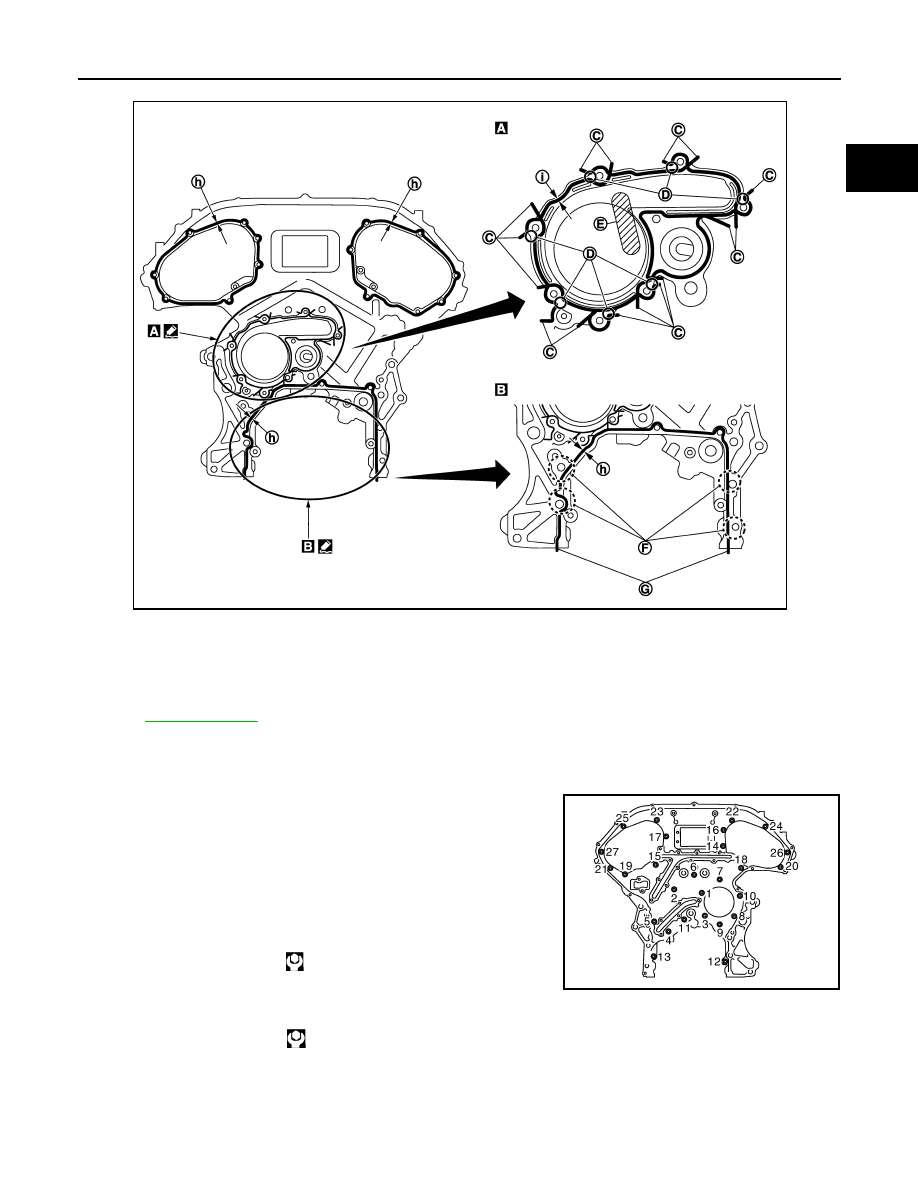
1.
Install rear timing chain case as follows:
a.
Install new O-rings (1) onto cylinder block.
b.
Apply liquid gasket with the tube presser (commercial service tool) to rear timing chain case back side as
shown in the figure.
Use Genuine RTV Silicone Sealant or equivalent. Refer to
GI-15, "Recommended Chemical Prod-
.
CAUTION:
• For
in the figure, completely wipe off liquid gasket extended on a portion touching at engine
coolant.
• Apply liquid gasket on installation position of water pump and cylinder head completely.
: Engine front
JPBIA0090ZZ
A
: Remove old liquid gasket that is stuck
B
: Bolt hole
JPBIA0051ZZ
: Engine front
JPBIA0090ZZ
REAR TIMING CHAIN CASE
EM-81
< DISASSEMBLY AND ASSEMBLY >
C
D
E
F
G
H
I
J
K
L
M
A
EM
N
P
O
c.
Align rear timing chain case with dowel pins (bank 1 and bank 2) on cylinder block and install rear timing
chain case.
• Check that O-rings stay in place during installation to cylinder block.
d.
Tighten mounting bolts in numerical order as shown in the fig-
ure.
• There are three types of mounting bolts. Refer to the following
for locating bolts.
e.
After all bolts are tightened, retighten them to the specified torque in numerical order shown in the figure.
• If liquid gasket protrudes, wipe it off immediately.
C.
Protrusion
D.
Clearance 1 mm (0.04 in)
E.
Do not protrude in this area
F.
Run along bolt hole inner side
G.
Protrusions at beginning and end of
gasket
h.
3.4 - 4.4 mm (0.134 - 173 in) dia
i.
2.6 - 2.8 mm (0.102 - 0.110 in) dia
Refer to
for symbol marks in the figure.
Bolt length:
Bolt position
20 mm (0.79 in)
: 1, 2, 3, 6, 7, 8, 9, 10
16 mm (0.63 in)
: 4, 5, 11, 12, 13
: 12.7 N·m (1.3 kg-m, 9 ft-lb)
16 mm (0.63 in)
: Except the above
: 15.0 N·m (1.5 kg-m, 11 ft-lb)
JPBIA0092ZZ
JPBIA0089ZZ
EM-82
< DISASSEMBLY AND ASSEMBLY >
REAR TIMING CHAIN CASE
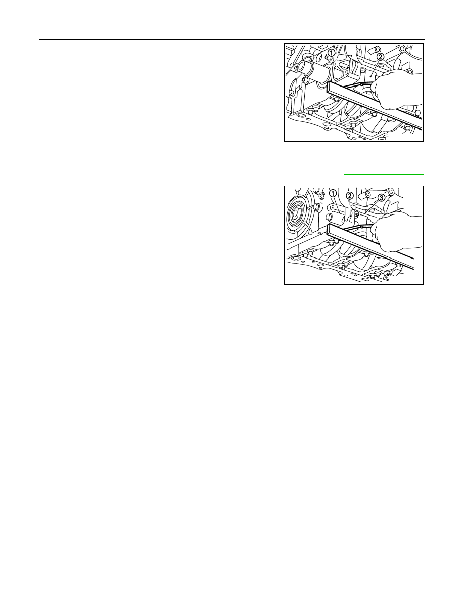
f.
After installing rear timing chain case, check the surface height
difference between the following parts on the oil pan (upper)
mounting surface.
• If not within the standard, repeat the installation procedure.
2.
Install water pump with new O-rings. Refer to
.
3.
Install timing chains, camshaft sprockets and front timing chain case. Refer to
.
• After installing front timing chain case, check the surface
height difference between the following parts on the oil pan
(upper) mounting surface.
• If not within the standard, repeat the installation procedure.
4.
Install in the reverse order of removal after this step.
1
: Rear timing chain case
2
: Lower cylinder block
Standard
Rear timing chain case to lower cylinder block:
–0.24 to 0.14 mm (–0.0094 to 0.0055 in)
1
: Front timing chain case
2
: Rear timing chain case
3
: Lower cylinder block
Standard
Front timing chain case to rear timing chain case:
–0.14 to 0.14 mm (–0.0055 to 0.0055 in)
JPBIA1363ZZ
JPBIA0093ZZ
Нет комментариевНе стесняйтесь поделиться с нами вашим ценным мнением.
Текст