Infiniti Q45 (FY33). Manual — part 413
SEM416FC
GI
MA
LC
EC
FE
AT
PD
FA
RA
BR
ST
RS
BT
HA
EL
IDX
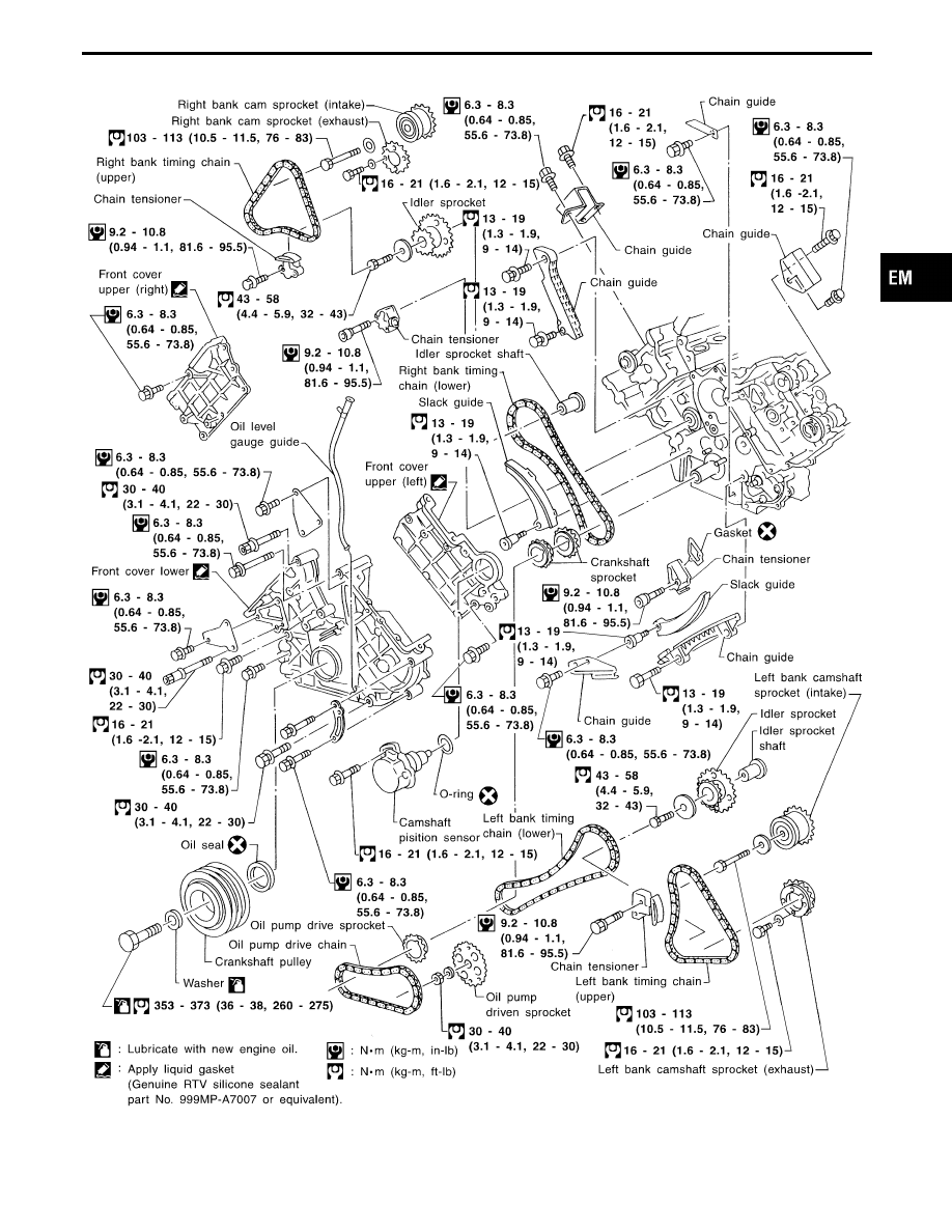
TIMING CHAIN
EM-13
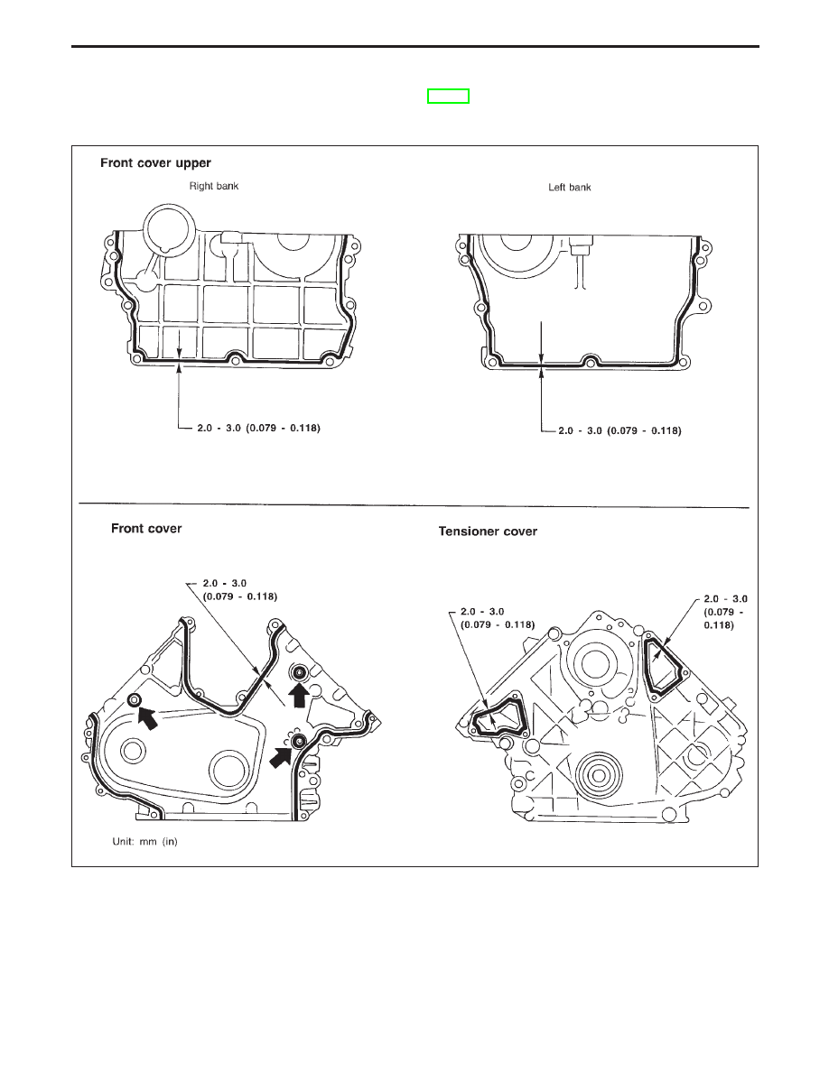
POSITION FOR APPLYING LIQUID GASKET
Refer to “Installation” in “OIL PAN” for installing oil pan (EM-12).
I
Before installation, wipe off the protruding sealant.
SEM417F
TIMING CHAIN
EM-14
CAUTION:
I
After removing timing chain, do not turn crankshaft and
camshaft separately, or valves will strike piston heads.
I
When installing camshafts, chain tensioners, oil seals, or
other sliding parts, lubricate contacting surfaces with new
engine oil.
I
Apply new engine oil to bolt threads and seat surfaces
when installing cylinder head, camshaft sprockets, crank-
shaft pulley, and camshaft brackets.
I
Before disconnecting fuel hose, release fuel pressure.
Refer to EC section (“Fuel Pressure Release”, “BASIC
SERVICE PROCEDURE”).
I
Do not spill engine coolant on drive belts.
SEM418F
Removal
1.
Remove engine assembly from vehicle. Refer to “ENGINE
REMOVAL” (EM-43).
2.
Remove the following parts.
I
Engine mounts
I
Alternator
I
Air conditioner compressor
I
Exhaust manifold
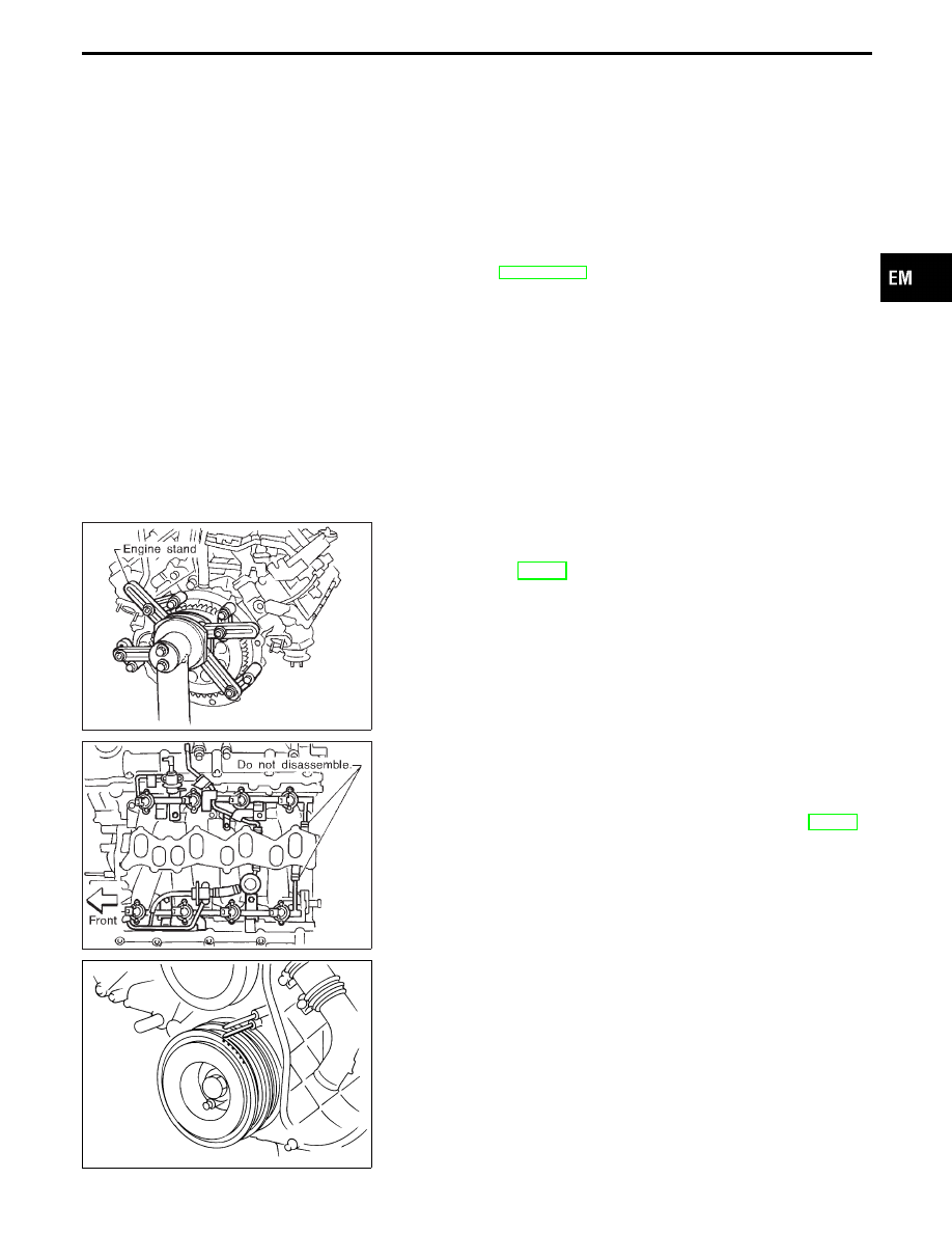
3.
Place engine assembly on stand.
4.
Remove intake manifold collector.
SEM419F
5.
Disconnect injector harness connector and remove fuel tube
assembly with injector.
I
Do not disassemble fuel hose.
6.
Remove intake manifold.
7.
Remove rocker cover. Refer to “CYLINDER HEAD” (EM-30).
SEM257G
8.
Set No. 1 piston at TDC on its compression stroke.
Align the timing mark on crankshaft pulley with timing indica-
tor on front cover.
GI
MA
LC
EC
FE
AT
PD
FA
RA
BR
ST
RS
BT
HA
EL
IDX
TIMING CHAIN
EM-15
SEM468F
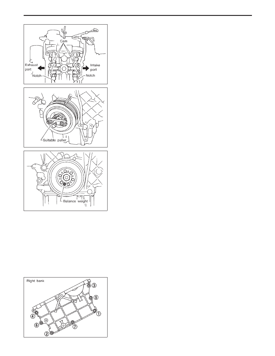
Make sure the intake camshaft lobe for the No. 1 cylinder faces the
intake port and the exhaust lobe faces the exhaust port.
Reference:
It is possible to confirm camshaft positions by checking notch posi-
tions on the camshaft when No. 1 piston is at TDC of the compres-
sion stroke. This is the position where cylinder head bolts can be
removed.
SEM420F
9.
Remove crankshaft pulley.
SEM469F
I
Do not remove the crankshaft pulley balance weight.
I
Do not disassemble the crankshaft pulley.
10. Remove camshaft position sensor assembly.
Do not disassemble camshaft position sensor unit.
SEM421F
11. Remove front cover upper.
I
Loosen bolts and nuts in the numerical order shown in the fig-
ure and then remove them.
TIMING CHAIN
Removal (Cont’d)
EM-16
Нет комментариевНе стесняйтесь поделиться с нами вашим ценным мнением.
Текст