Infiniti Q45 (FY33). Manual — part 38
SAT909I
SAT525I
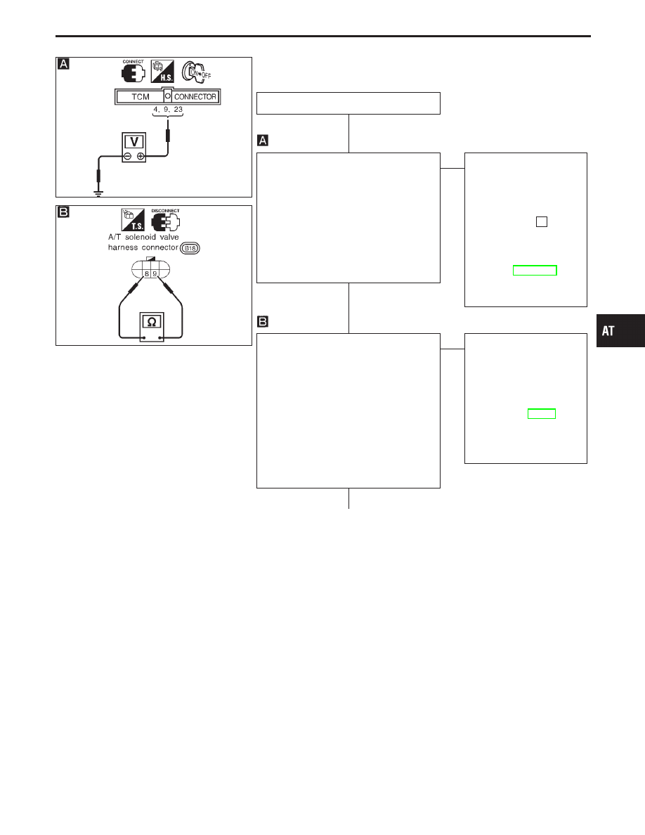
DIAGNOSTIC PROCEDURE
INSPECTION START
CHECK TCM POWER SOURCE.
1. Turn ignition switch to “ON” position.
(Do not start engine.)
2. Check voltage between TCM terminals
q
4
,
q
9
,
q
23
and ground.
Voltage: Battery voltage
3. Turn ignition switch to “OFF” position.
4. Check voltage between TCM terminal
q
23
and ground.
Voltage: Battery voltage
OK
E
NG
Check the following items:
I
Harness for short or
open between ignition
switch and TCM (Main
harness)
I
10A fuse [No.
28
,
located in the fuse block
(J/B)]
I
Ignition switch
Refer to EL section
(“POWER SUPPLY
ROUTING”).
CHECK A/T FLUID TEMPERATURE
SENSOR WITH TERMINAL CORD
ASSEMBLY.
1. Turn ignition switch to “OFF” position.
2. Disconnect terminal cord assembly con-
nector at the end of A/T assembly.
3. Check resistance between terminals
q
8
and
q
9
when A/T is cold.
Resistance:
Cold [20°C (68°F)]
Approximately 2.5 k
Ω
4. Reinstall any part removed.
OK
E
NG
1. Remove oil pan.
2. Check the following
items:
I
A/T fluid temperature
sensor
Refer to “Component
Inspection”, AT-150.
I
Harness of terminal cord
assembly for short or
open
q
A
(Go to next page.)
GI
MA
EM
LC
EC
FE
PD
FA
RA
BR
ST
RS
BT
HA
EL
IDX
TROUBLE DIAGNOSIS FOR BATT/FLUID TEMP SEN
A/T Fluid Temperature Sensor Circuit and TCM
Power Source (Cont’d)
H
H
H
AT-149
SAT738J
SAT913IA
SAT914I
q
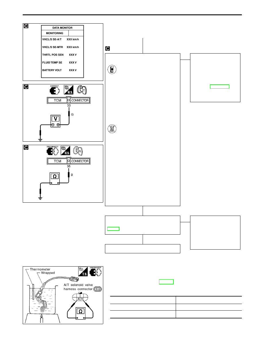
A
CHECK INPUT SIGNAL OF A/T FLUID
TEMPERATURE SENSOR.
1. Start engine.
2. Select “TCM INPUT SIGNALS”
in “DATA MONITOR” mode for
A/T with CONSULT-II.
3. Read out the value of “FLUID
TEMP SE”.
Voltage:
Cold [20°C (68°F)]
→
Hot [80°C (176°F)]:
Approximately
1.5V
→
0.5V
-------------------------------------------------------------------------------------------------------------------------------------- OR --------------------------------------------------------------------------------------------------------------------------------------
1. Start engine.
2. Check voltage between TCM
terminal
q
33
and ground while
warming up A/T.
Voltage:
Cold [20°C (68°F)]
→
Hot [80°C (176°F)]:
Approximately
1.5V
→
0.5V
3. Turn ignition switch to “OFF”
position.
4. Disconnect TCM harness con-
nector.
5. Check resistance between ter-
minal
q
35
and ground.
Continuity should exist.
OK
E
NG
Check the following item:
I
Harness for short or
open between TCM,
ECM and terminal cord
assembly (Main harness)
I
Ground circuit for ECM
Refer to EC section
(“TROUBLE DIAGNOSIS
FOR POWER SUPPLY”).
Perform DIAGNOSTIC TROUBLE CODE
(DTC) CONFIRMATION PROCEDURE,
AT-148.
OK
E
NG
1. Perform TCM input/
output signal inspection.
2. If NG, recheck TCM pin
terminals for damage or
loose connection with
harness connector.
INSPECTION END
SAT527I
COMPONENT INSPECTION
A/T fluid temperature sensor
I
For removal, refer to AT-195.
I
Check resistance between terminals
q
8
and
q
9
while changing
temperature as shown at left.
Temperature °C (°F)
Resistance
20 (68)
Approximately 2.5 k
Ω
80 (176)
Approximately 0.3 k
Ω
TROUBLE DIAGNOSIS FOR BATT/FLUID TEMP SEN
A/T Fluid Temperature Sensor Circuit and TCM
Power Source (Cont’d)
H
H
H
AT-150
SAT568I
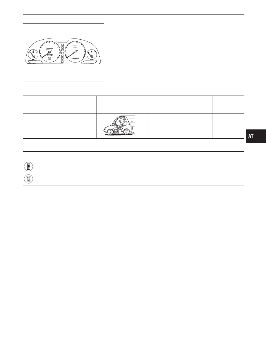
Vehicle Speed Sensor
⋅
MTR
DESCRIPTION
The vehicle speed sensor
⋅
MTR is built into the speedometer
assembly. The sensor functions as an auxiliary device to the revo-
lution sensor when it is malfunctioning. The TCM will then use a
signal sent from the vehicle speed sensor
⋅
MTR.
TCM TERMINALS AND REFERENCE VALUE
Remarks: Specification data are reference values.
Terminal
No.
Wire color
Item
Condition
Judgement
standard
(Approx.)
27
P/L
Vehicle speed
sensor
When moving vehicle at 2 to 3 km/h
(1 to 2 MPH) for 1 m (3 ft) or more.
Voltage varies
between less
than 1V and
more than 4.5V
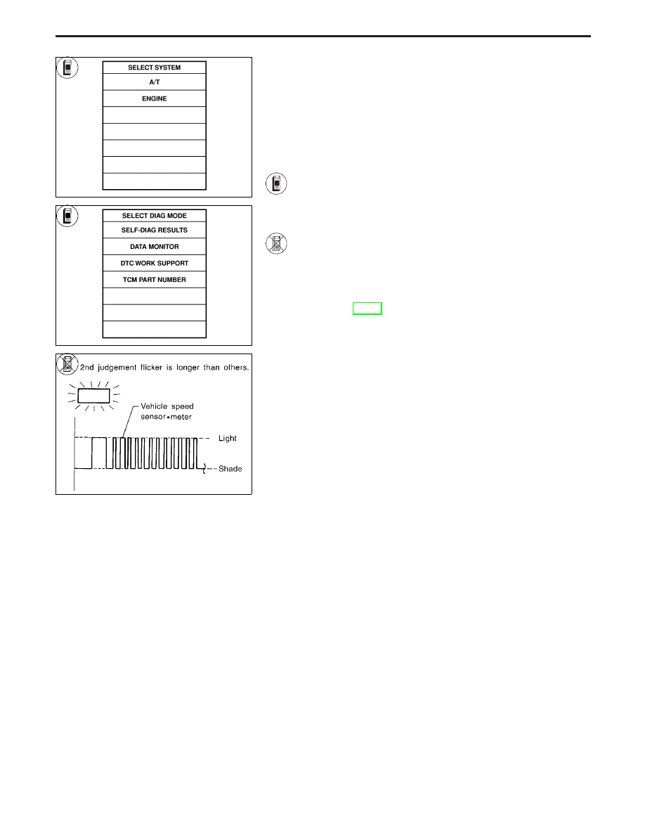
ON BOARD DIAGNOSIS LOGIC
Diagnostic trouble code
Malfunction is detected when ...
Check item (Possible cause)
: VHCL SPEED SEN
⋅
MTR
TCM does not receive the proper volt-
age signal from the sensor.
I
Harness or connectors
(The sensor circuit is open or
shorted.)
I
Vehicle speed sensor
: 2nd judgement flicker
GI
MA
EM
LC
EC
FE
PD
FA
RA
BR
ST
RS
BT
HA
EL
IDX
TROUBLE DIAGNOSIS FOR VHCL SPEED SEN
⋅
MTR
AT-151
SAT014K
SAT971J
SAT569I
DIAGNOSTIC TROUBLE CODE (DTC) CONFIRMA-
TION PROCEDURE
CAUTION:
I
Always drive vehicle at a safe speed.
I
If conducting this “DTC CONFIRMATION PROCEDURE”
again, always turn ignition switch “OFF” and wait at least
5 seconds before continuing.
After the repair, perform the following procedure to confirm the
malfunction is eliminated.
1)
Turn ignition switch “ON” and select “DATA MONITOR”
mode for “A/T” with CONSULT-II.
2)
Start engine and accelerate vehicle from 0 to 25 km/h (0
to 16 MPH).
------------------------------------------------------------------------------------------------------------------------------------------------------------------------------------------------------------------------------------------------------ OR ------------------------------------------------------------------------------------------------------------------------------------------------------------------------------------------------------------------------------------------------------
1)
Start engine.
2)
Drive vehicle under the following conditions:
Selector lever in “D” and vehicle speed higher than 25
km/h (16 MPH).
3)
Perform self-diagnosis.
Refer to TCM SELF-DIAGNOSTIC PROCEDURE (No
Tools), AT-49.
TROUBLE DIAGNOSIS FOR VHCL SPEED SEN
⋅
MTR
Vehicle Speed Sensor
⋅
MTR (Cont’d)
AT-152
Нет комментариевНе стесняйтесь поделиться с нами вашим ценным мнением.
Текст