Infiniti Q45 (FY33). Manual — part 39
SAT738J
SAT943IA
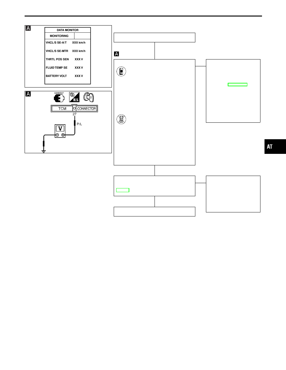
DIAGNOSTIC PROCEDURE
INSPECTION START
CHECK INPUT SIGNAL.
1. Start engine.
2. Select “TCM INPUT SIGNALS”
in “DATA MONITOR” mode for
“A/T” with CONSULT-II.
3. Read out the value of “VHCL/S
SE
⋅
MTR” while driving.
Check the value changes
according to driving speed.
-------------------------------------------------------------------------------------------------------------------------------------- OR --------------------------------------------------------------------------------------------------------------------------------------
1. Start engine.
2. Check voltage between TCM
terminal
q
27
and ground while
driving at 2 to 3 km/h (1 to 2
MPH) for 1 m (3 ft) or more.
Voltage:
Voltage varies between less
than 1V and more than
4.5V.
OK
E
NG
Check the following items:
I
Vehicle speed sensor
and ground circuit for
vehicle speed sensor
Refer to EL section
(“METERS AND
GAUGES”).
I
Harness for short or
open between TCM and
vehicle speed sensor
(Main harness)
Perform DIAGNOSTIC TROUBLE CODE
(DTC) CONFIRMATION PROCEDURE,
AT-152.
OK
E
NG
1. Perform TCM input/
output signal inspection.
2. If NG, recheck TCM pin
terminals for damage or
loose connection with
harness connector.
INSPECTION END
GI
MA
EM
LC
EC
FE
PD
FA
RA
BR
ST
RS
BT
HA
EL
IDX
TROUBLE DIAGNOSIS FOR VHCL SPEED SEN
⋅
MTR
Vehicle Speed Sensor
⋅
MTR (Cont’d)
H
H
H
AT-153
SAT557IA
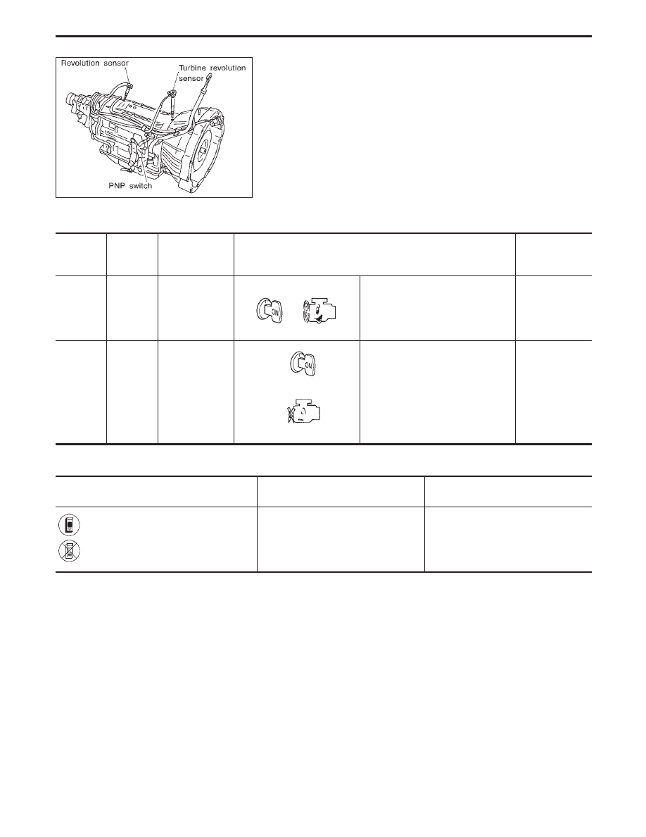
Turbine Revolution Sensor
DESCRIPTION
The turbine revolution sensor detects input shaft rpm (revolutions
per minute). It is located on the input side of the automatic trans-
mission. The vehicle speed sensor A/T (Revolution sensor) is
located on the output side of the automatic transmission. With the
two sensors, input and output shaft rpms are accurately detected.
The result is optimal shift timing during deceleration and improved
shifting.
TCM TERMINALS AND REFERENCE VALUE
Remarks: Specification data are reference values.
Terminal
No.
Wire color
Item
Condition
Judgement
standard
(Approx.)
26
Y
Turbine revolu-
tion sensor
(Measure in AC
range)
When engine is running at 1,000
rpm
1.2V
Voltage rises
gradually in
response to
engine speed.
35
B
Throttle position
sensor
(Ground)
—
0V
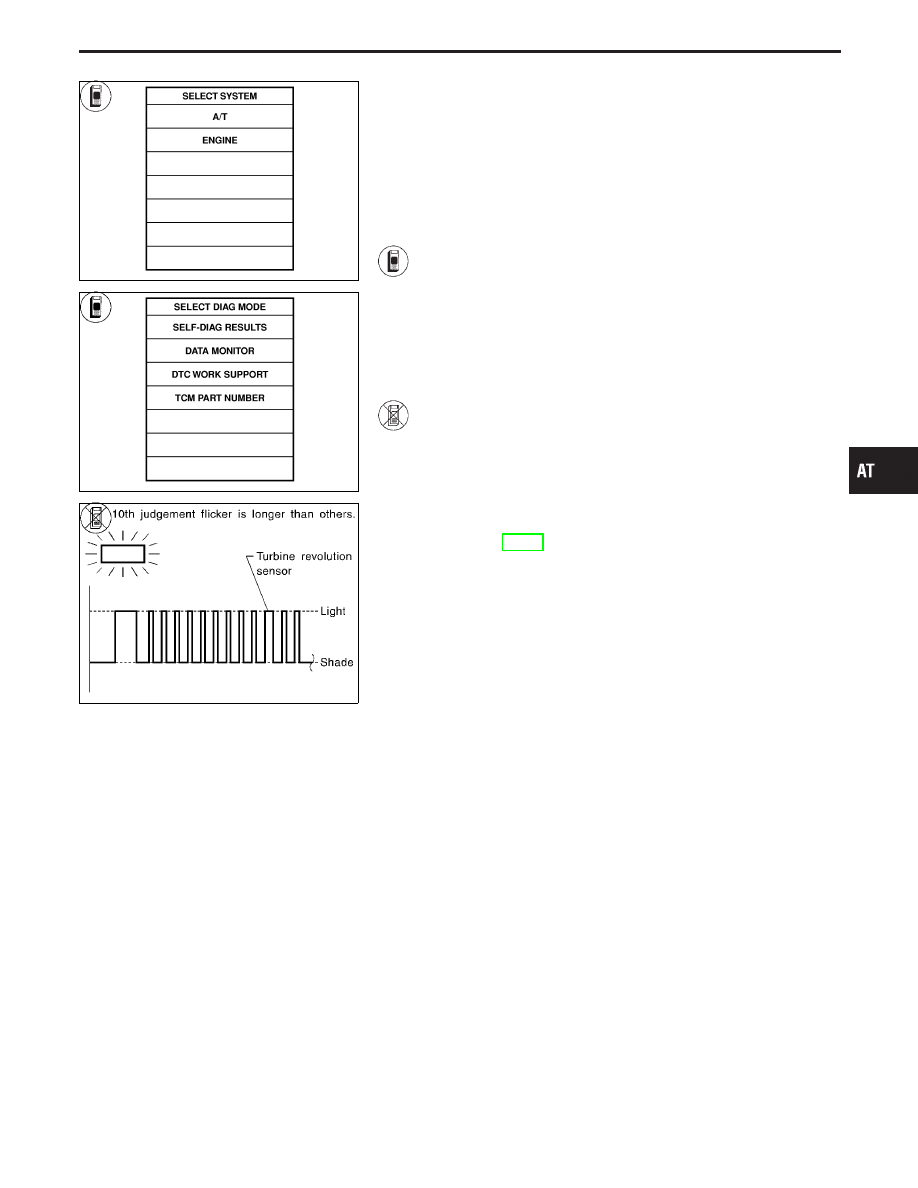
ON BOARD DIAGNOSIS LOGIC
Diagnostic trouble code
Malfunction is detected when ...
Check item
(Possible cause)
: TURBINE REV
TCM does not receive the proper volt-
age signal from the sensor.
I
Harness or connectors
(The sensor circuit is open or short.)
I
Turbine revolution sensor
: 10th judgement flicker
TROUBLE DIAGNOSIS FOR TURBINE REV
AT-154
SAT014K
SAT971J
SAT635I
DIAGNOSTIC TROUBLE CODE (DTC) CONFIRMATION
PROCEDURE
CAUTION:
I
Always drive vehicle at a safe speed.
I
If conducting this “DTC CONFIRMATION PROCEDURE”
again, always turn ignition switch “OFF” and wait at least
5 seconds before continuing.
After the repair, perform the following procedure to confirm the
malfunction is eliminated.
1)
Start engine.
2)
Select “DATA MONITOR” mode for “A/T” with CON-
SULT-II.
3)
Drive vehicle under the following conditions:
Selector lever in “D”, vehicle speed higher than 40 km/h
(25 MPH), engine speed higher than 1,500 rpm, throttle
opening greater than 1.0/8 of the full throttle position and
driving for more than 5 seconds.
------------------------------------------------------------------------------------------------------------------------------------------------------------------------------------------------------------------------------------------------------ OR ------------------------------------------------------------------------------------------------------------------------------------------------------------------------------------------------------------------------------------------------------
1)
Start engine.
2)
Drive vehicle under the following conditions:
Selector lever in “D”, vehicle speed higher than 40 km/h
(25 MPH), engine speed higher than 1,500 rpm, throttle
opening greater than 1/8 of the full throttle position and
driving for more than 5 seconds.
3)
Perform self-diagnosis.
Refer to TCM SELF-DIAGNOSTIC PROCEDURE (No
Tools), AT-49.
GI
MA
EM
LC
EC
FE
PD
FA
RA
BR
ST
RS
BT
HA
EL
IDX
TROUBLE DIAGNOSIS FOR TURBINE REV
Turbine Revolution Sensor (Cont’d)
AT-155
SAT740J
SAT059J
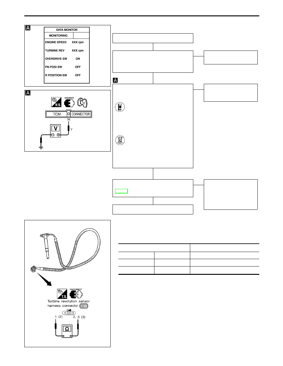
DIAGNOSTIC PROCEDURE
INSPECTION START
CHECK TURBINE REVOLUTION SEN-
SOR.
Refer to “COMPONENT INSPECTION”
below.
OK
E
NG
Repair or replace
turbine revolution sensor.
CHECK INPUT SIGNAL.
1. Turn ignition switch to “START” position
and start engine.
2.
I
Select “TCM INPUT SIGNALS”
in “DATA MONITOR” mode for
“A/T” with CONSULT-II.
I
Read out the value of “TURBINE
REV”.
I
Check the value changes
according to engine speed.
-------------------------------------------------------------------------------------------------------------------------------------- OR --------------------------------------------------------------------------------------------------------------------------------------
Check voltage between TCM ter-
minal
q
26
and ground.
(Measure in AC range.)
Voltage:
Approximately 1.2V
(Voltage rises gradually in
response to engine speed.)
OK
E
NG
Check harness for short or
open between TCM and
turbine revolution sensor.
Perform DIAGNOSTIC TROUBLE CODE
(DTC) CONFIRMATION PROCEDURE,
AT-155.
OK
E
NG
1. Perform TCM input/
output signal inspection.
2. If NG, recheck TCM pin
terminals for damage or
loose connection with
harness connector.
INSPECTION END
SAT573I
COMPONENT INSPECTION
Turbine revolution sensor
I
Check resistance between terminals
q
1
,
q
2
and
q
3
.
Terminal No.
Resistance
q
1
q
2
2.4 - 2.8 k
Ω
q
1
q
3
No continuity
q
2
q
3
No continuity
TROUBLE DIAGNOSIS FOR TURBINE REV
Turbine Revolution Sensor (Cont’d)
H
H
H
H
AT-156
Нет комментариевНе стесняйтесь поделиться с нами вашим ценным мнением.
Текст