Infiniti Q45 (FY33). Manual — part 236
SEF623U
SEC056C
SEF877T
SEF625U
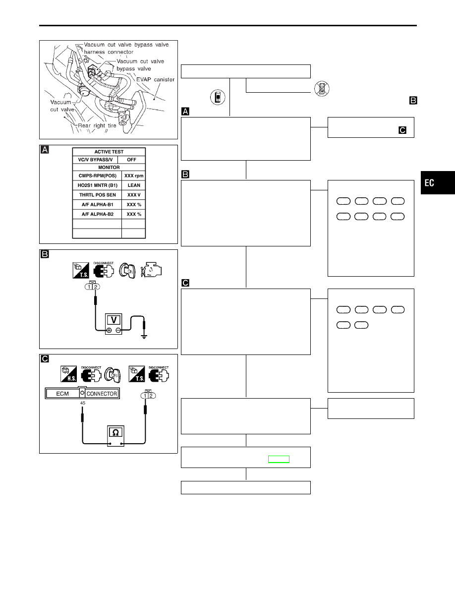
DIAGNOSTIC PROCEDURE
INSPECTION START
E
Go to CHECK POWER SUPPLY
.
CHECK CIRCUIT.
1. Perform “VC/V BYPASS/V” in “ACTIVE
TEST” mode.
2. Make sure that clicking sound is heard
from the vacuum cut bypass valve.
NG
E
OK
Go to “CHECK COMPO-
NENT” after procedure
.
CHECK POWER SUPPLY.
1. Turn ignition switch “OFF”.
2. Disconnect vacuum cut valve bypass
valve harness connector.
3. Turn ignition switch “ON”.
4. Check voltage between terminal
q
2
and
ground with CONSULT-II or tester.
Voltage: Battery voltage
OK
E
NG
Check the following.
I
Harness connectors
C14
,
B64
,
B65
,
B178
I
Harness connectors
B102
,
F64
,
F63
,
M49
I
10A fuse
I
Harness for open or short
between vacuum cut
valve bypass valve and
fuse
If NG, repair harness or
connectors.
CHECK OUTPUT SIGNAL CIRCUIT.
1. Turn ignition switch “OFF”.
2. Disconnect ECM harness connector.
3. Check harness continuity between ECM
terminal
q
45
and terminal
q
1
.
Continuity should exist.
If OK, check harness for short to ground
and short to power.
OK
E
NG
Check the following.
I
Harness connectors
F64
,
B102
,
B178
,
B65
I
Harness or connectors
B64
,
C14
I
Harness for open or short
between vacuum cut
valve bypass valve and
ECM
If NG, repair open circuit or
short to ground or short to
power in harness or con-
nectors.
CHECK COMPONENT
(Vacuum cut valve bypass valve).
Refer to “COMPONENT INSPECTION” on
next page.
OK
E
NG
Replace vacuum cut valve
bypass valve.
Perform “TROUBLE DIAGNOSIS FOR
INTERMITTENT INCIDENT”, EC-117.
INSPECTION END
GI
MA
EM
LC
FE
AT
PD
FA
RA
BR
ST
RS
BT
HA
EL
IDX
TROUBLE DIAGNOSIS FOR DTC P1490
Vacuum Cut Valve Bypass Valve (Circuit)
(Cont’d)
H
H
H
H
H
H
EC-473
SEC057C
SEF351Q
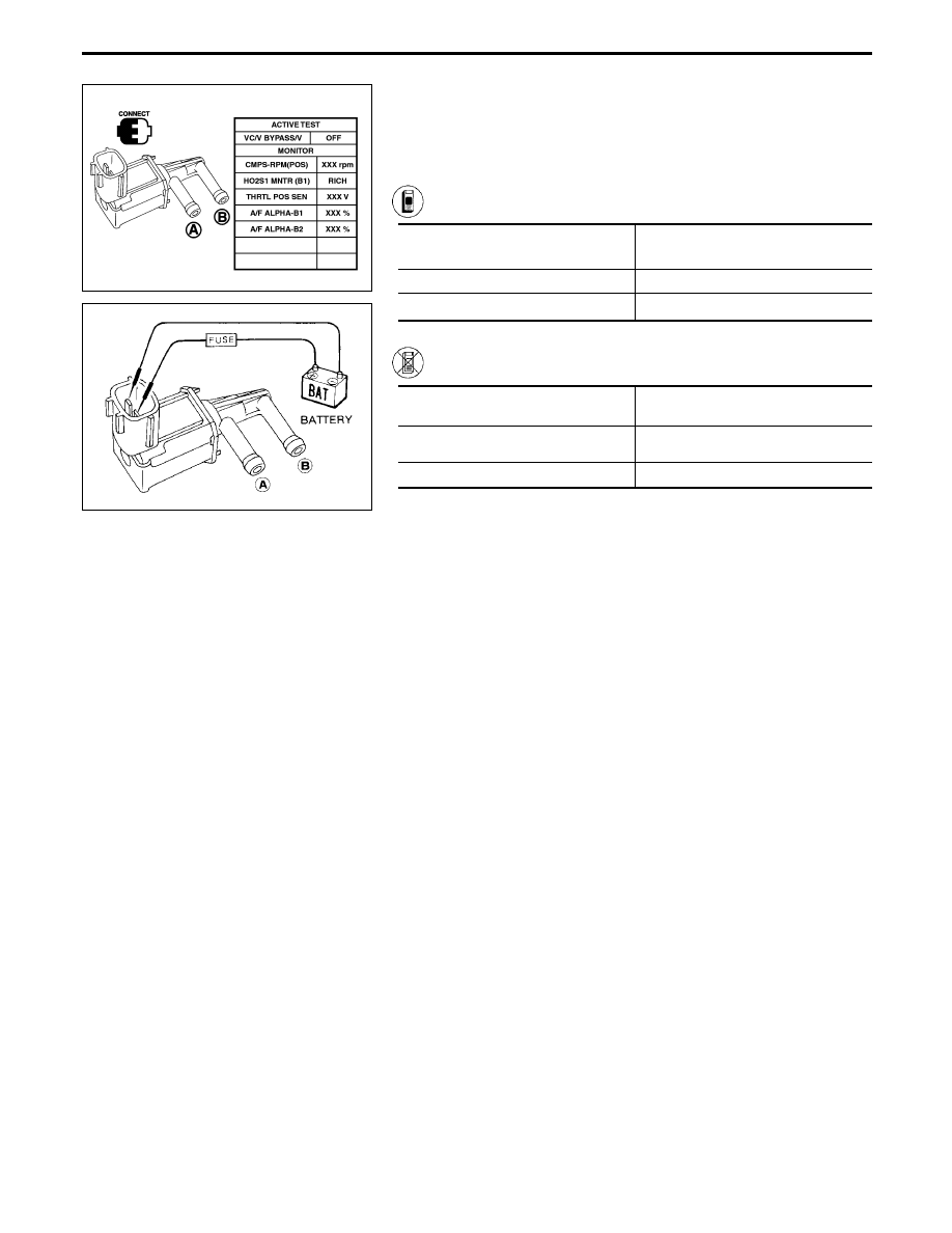
COMPONENT INSPECTION
Vacuum cut valve bypass valve
Check air passage continuity.
Perform “VC/V BYPASS/V” in “ACTIVE TEST” mode.
Condition
VC/V BYPASS/V
Air passage continuity
between
q
A
and
q
B
ON
Yes
OFF
No
------------------------------------------------------------------------------------------------------------------------------------------------------------------------------------------------------------------------------------------------------ OR ------------------------------------------------------------------------------------------------------------------------------------------------------------------------------------------------------------------------------------------------------
Condition
Air passage continuity
between
q
A
and
q
B
12V direct current supply between
terminals
Yes
No supply
No
If NG or operation takes more than 1 second, replace vacuum cut
valve bypass valve.
TROUBLE DIAGNOSIS FOR DTC P1490
Vacuum Cut Valve Bypass Valve (Circuit)
(Cont’d)
EC-474
SEF623U
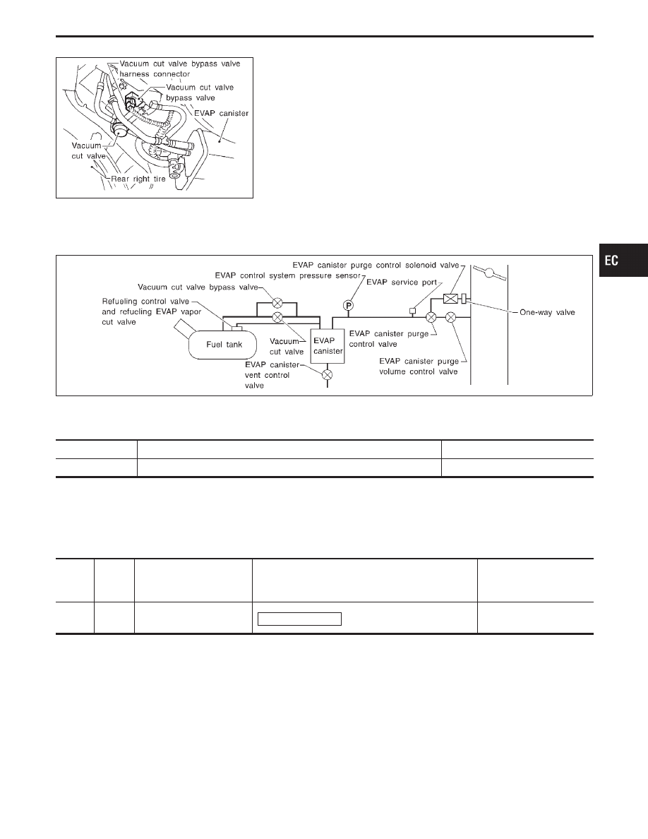
Vacuum Cut Valve Bypass Valve
COMPONENT DESCRIPTION
The vacuum cut valve and vacuum cut valve bypass valve are
installed in parallel on the EVAP purge line between the fuel tank
and the EVAP canister.
The vacuum cut valve prevents the intake manifold vacuum from
being applied to the fuel tank.
The vacuum cut valve bypass valve is a solenoid type valve and
generally remains closed. It opens only for on board diagnosis.
The vacuum cut valve bypass valve responds to signals from the
ECM. When the ECM sends an ON (ground) signal, the valve is
opened. The vacuum cut valve is then bypassed to apply intake
manifold vacuum to the fuel tank.
EVAPORATIVE EMISSION SYSTEM DIAGRAM
SEF850U
CONSULT-II REFERENCE VALUE IN DATA MONITOR MODE
Specification data are reference values.
MONITOR ITEM
CONDITION
SPECIFICATION
VC/V BYPASS/V
I
Ignition switch: ON
OFF
ECM TERMINALS AND REFERENCE VALUE
Specification data are reference values and are measured between each terminal and ground.
CAUTION:
Do not use ECM ground terminals when measuring voltage. Doing so may result in damage to the
ECM’s transistor. Use a ground other than ECM terminals such as the body ground.
TER-
MINAL
NO.
WIRE
COLOR
ITEM
CONDITION
DATA
(DC Voltage)
45
LG/B
Vacuum cut valve bypass
valve
Ignition switch “ON”
BATTERY VOLTAGE
(11 - 14V)
GI
MA
EM
LC
FE
AT
PD
FA
RA
BR
ST
RS
BT
HA
EL
IDX
TROUBLE DIAGNOSIS FOR DTC P1491
EC-475
ON BOARD DIAGNOSIS LOGIC
Diagnostic Trouble
Code No.
Malfunction is detected when .
Check Items
(Possible Cause)
P1491
0311
I
Vacuum cut valve bypass valve does not operate
properly.
I
Vacuum cut valve bypass valve
I
Vacuum cut valve
I
Bypass hoses for clogging
I
EVAP control system pressure sensor
I
EVAP canister vent control valve
I
Hose between fuel tank and vacuum cut valve
clogged
I
Hose between vacuum cut valve and EVAP canis-
ter clogged
I
EVAP canister
I
EVAP purge port of fuel tank for clogging
SEF809X
SEF810X
SEC058C
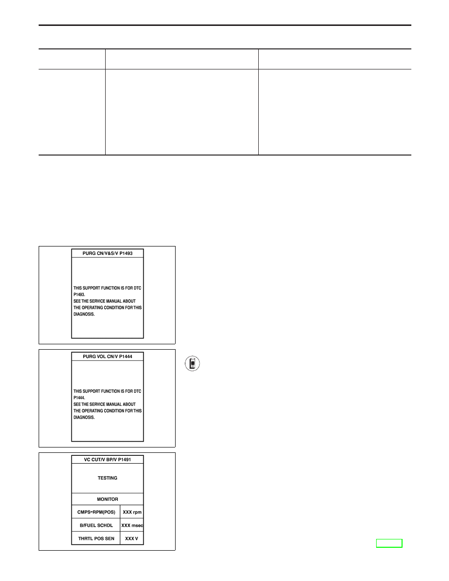
DIAGNOSTIC TROUBLE CODE CONFIRMATION
PROCEDURE
CAUTION:
Always drive vehicle at a safe speed.
NOTE:
If “DIAGNOSTIC TROUBLE CODE CONFIRMATION PROCE-
DURE” has been previously conducted, always turn ignition
switch “OFF” and wait at least 5 seconds before conducting
the next test.
TESTING CONDITION:
I
Always perform test at temperature of 0 to 30°C (32 to
86°F).
1) Turn ignition switch “ON”.
2) Start engine and warm it up to normal operating tem-
perature.
3) Turn ignition switch “OFF” and wait at least 5 seconds.
4) Start engine (TCS switch “OFF”) and let it idle for at
least 90 seconds.
5) Select “PURG CN/V & S/V P1493” of “EVAPORATIVE
SYSTEM” in “DTC WORK SUPPORT” mode with CON-
SULT-II.
6) Touch “START”.
7) When the following conditions are met, “TESTING” will
be displayed on the CONSULT-II screen. Maintain the
conditions continuously until “TESTING” changes to
“COMPLETED”. (It will take at least 30 seconds.)
CMPS-RPM (POS): 900 - 6,300 rpm
Vehicle speed: 36 - 120 km/h (22 - 75 MPH)
B/FUEL SCHDL: 2 - 4.8 msec
Selector lever: Suitable position
If “TESTING” is not displayed after 5 minutes, retry
from step 3).
8) Make sure that “OK” is displayed after touching “SELF-
DIAG RESULTS”. If “NG” is displayed, refer to
“TROUBLE DIAGNOSIS FOR DTC P1493”, EC-488.
TROUBLE DIAGNOSIS FOR DTC P1491
Vacuum Cut Valve Bypass Valve (Cont’d)
EC-476
Нет комментариевНе стесняйтесь поделиться с нами вашим ценным мнением.
Текст