Infiniti Q45 (FY33). Manual — part 234
SEF814X
PEF929V
SEF813X
PEF669U
SEC050C
DIAGNOSTIC TROUBLE CODE CONFIRMATION
PROCEDURE
NOTE:
I
If DTC P1448 is displayed with P0440, P1440, perform
TROUBLE DIAGNOSIS FOR DTC P1448 first.
I
If “DIAGNOSTIC TROUBLE CODE CONFIRMATION PRO-
CEDURE” has been previously conducted, always turn
ignition switch “OFF” and wait at least 5 seconds before
conducting the next test.
TESTING CONDITION:
I
Perform “DTC WORK SUPPORT” when the fuel level is
less than 3/4 full. And vehicle is placed on a flat level sur-
face.
I
Always perform test at temperature of 0 to 30°C (32 to
86°F).
I
It is better that fuel level is low.
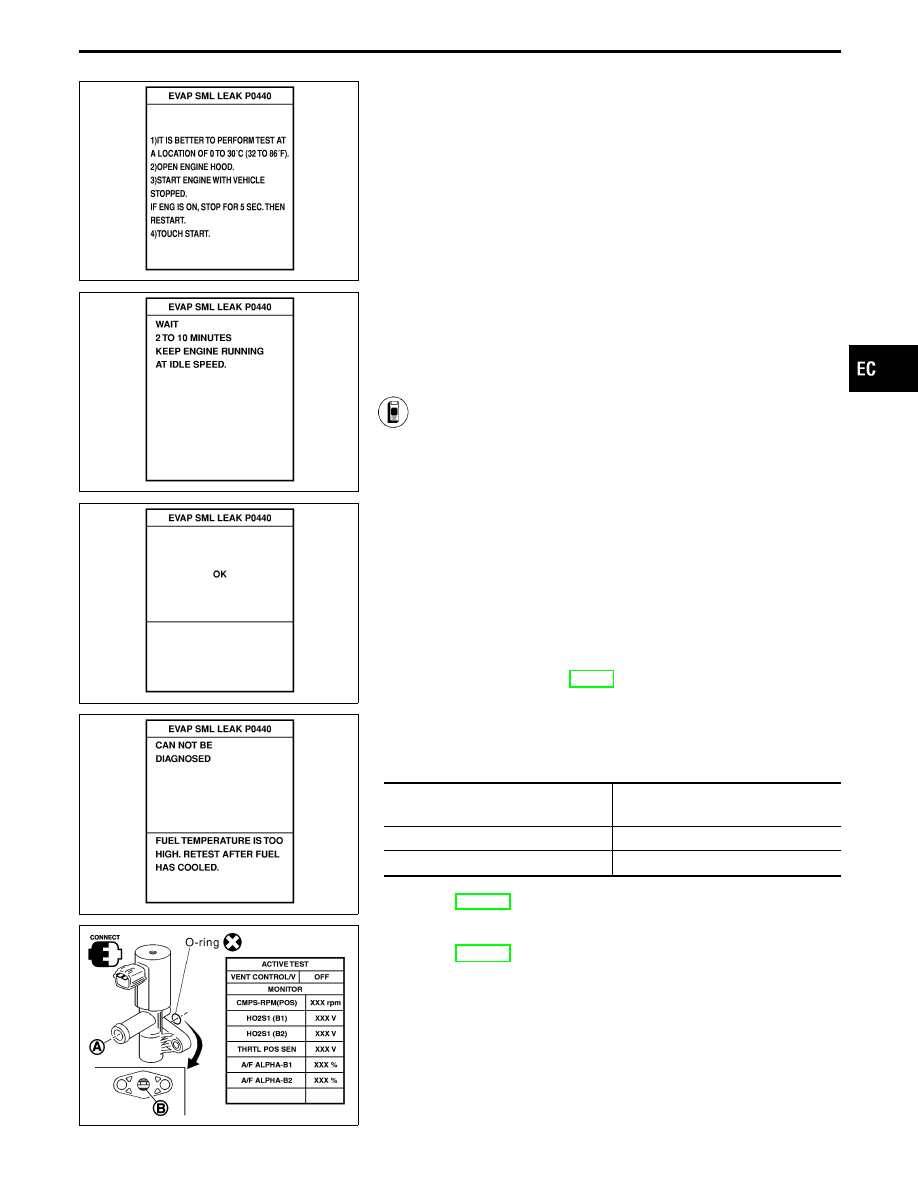
1) Turn ignition switch “ON”.
2) Select “EVAP SML LEAK P0440” of “EVAPORATIVE
SYSTEM” in “DTC WORK SUPPORT” mode with CON-
SULT-II.
Follow the instruction displayed.
3) Make sure that “OK” is displayed.
If “NG” is displayed, go to following step.
NOTE:
I
If the CONSULT-II screen shown at left (“CAN NOT
BE DIAGNOSED”) is displayed, stop the engine and
stabilize the vehicle temperature at 25°C (77°F) or
cooler. After “FUEL T/TMP SE” becomes less than
30°C (86°F), retest.
(Use a fan to reduce the stabilization time.)
I
If the engine speed cannot be maintained within the
range on the CONSULT-II screen, go to “BASIC
INSPECTION”, EC-91.
4) Disconnect hose from water separator.
5) Select “VENT CONTROL/V” of “ACTIVE TEST” mode
with CONSULT-II.
6) Touch “ON” and “OFF” alternately.
7) Make sure the following.
Condition
VENT CONTROL/V
Air passage continuity
between
q
A
and
q
B
ON
No
OFF
Yes
If the result is NG, go to “DIAGNOSTIC PROCEDURE”,
EC-467.
If the result is OK, go to “DIAGNOSTIC PROCEDURE”
for
“TROUBLE
DIAGNOSIS
FOR
DTC
P0440”,
GI
MA
EM
LC
FE
AT
PD
FA
RA
BR
ST
RS
BT
HA
EL
IDX
TROUBLE DIAGNOSIS FOR DTC P1448
Evaporative Emission (EVAP) Canister Vent
Control Valve (Open) (Cont’d)
EC-465
AEC783A
------------------------------------------------------------------------------------------------------------------------------------------------------------------------------------------------------------------------------------------------------ OR ------------------------------------------------------------------------------------------------------------------------------------------------------------------------------------------------------------------------------------------------------
OVERALL FUNCTION CHECK
Use this procedure to check the overall function of the EVAP can-
ister vent control valve circuit. During this check, a DTC might not
be confirmed.
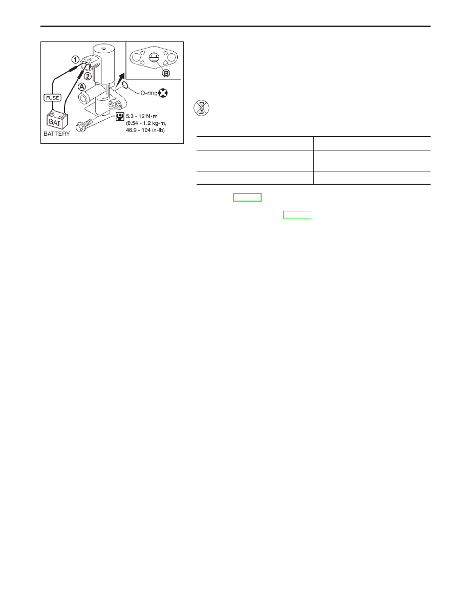
1) Disconnect hose from water separator.
2) Disconnect EVAP canister vent control valve harness
connector.
3) Verify the following.
Condition
Air passage continuity
12V direct current supply between
terminals
q
1
and
q
2
No
No supply
Yes
If the result is NG, go to “DIAGNOSTIC PROCEDURE”,
EC-467.
If the result is OK, go to “TROUBLE DIAGNOSIS FOR
DTC P0440”, EC-298.
TROUBLE DIAGNOSIS FOR DTC P1448
Evaporative Emission (EVAP) Canister Vent
Control Valve (Open) (Cont’d)
EC-466
SEF419U
SEF623U
SEF596U
SEF427U
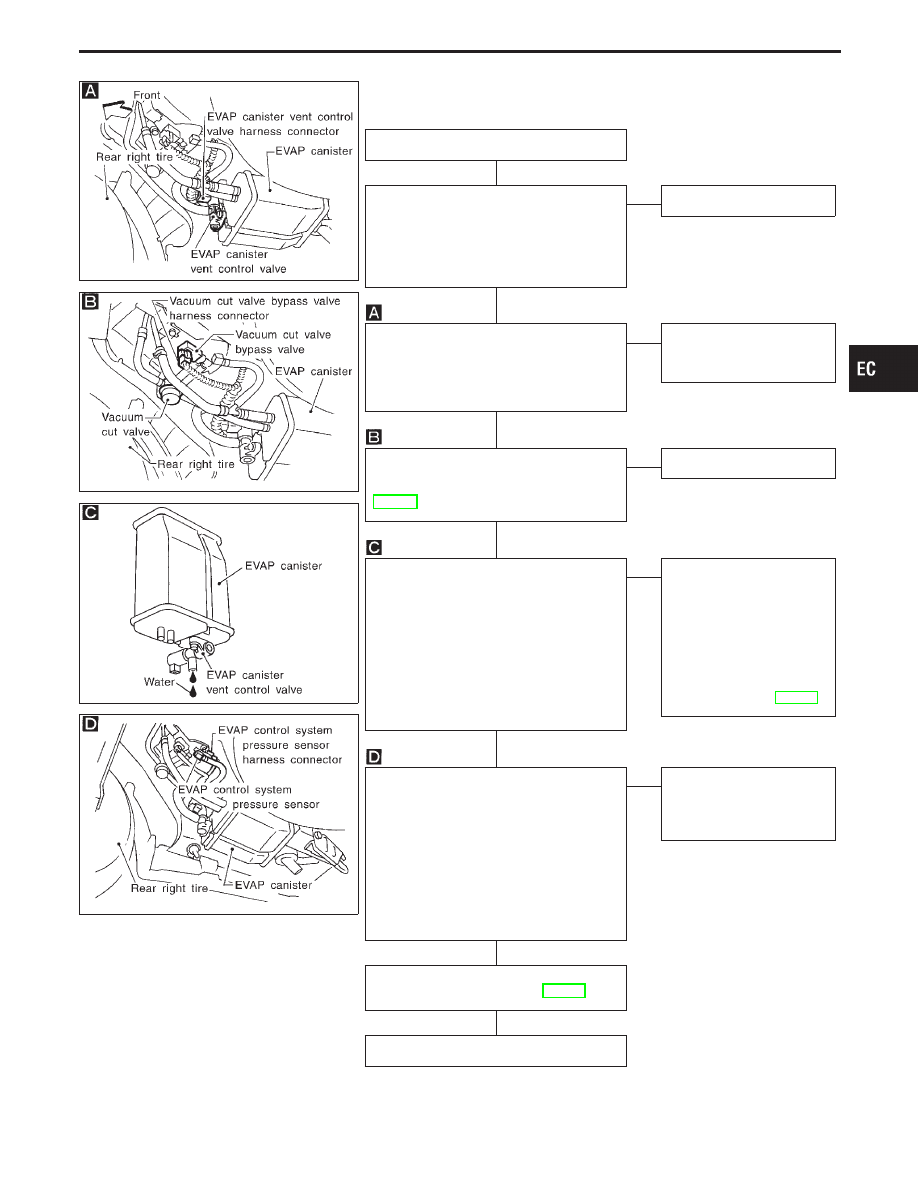
DIAGNOSTIC PROCEDURE
INSPECTION START
CHECK RUBBER TUBE FOR DISCON-
NECTION.
Check disconnection of rubber tube to
EVAP canister vent control valve and
clean the rubber hose and/or vent control
valve then install properly.
OK
E
NG
Repair or clean.
CHECK COMPONENT
(EVAP canister vent control valve and
O-ring).
Refer to “COMPONENT INSPECTION” on
next page.
OK
E
NG
Replace EVAP canister
vent control valve and
O-ring.
CHECK COMPONENT
(Vacuum cut valve).
Refer to “COMPONENT INSPECTION”,
EC-474.
OK
E
NG
Replace vacuum cut valve.
CHECK IF EVAP CANISTER IS SATU-
RATED WITH WATER.
1. Remove EVAP canister with the vent
control valve attached.
2. Check if water will drain from the EVAP
canister.
If it will, weigh the EVAP canister with
the vent control valve attached.
If the weight is:
More than 1.8 kg (4.0 lb)
→
NG
Less than 1.8 kg (4.0 lb)
→
OK
OK
E
NG
Replace EVAP canister
and check the following.
1. Check hose connections
to the EVAP canister
and water separator for
clogging and poor con-
nection.
2. Check water separator.
Refer to “COMPONENT
INSPECTION”, EC-469.
CHECK COMPONENT
(EVAP control system pressure sensor).
1. Check for disconnection of hose con-
nected to the sensor.
2. Check sensor harness connector for
water.
Water should not exist.
3. Check EVAP control system pressure
sensor.
Refer to “COMPONENT INSPECTION” on
next page.
OK
E
NG
Replace EVAP control sys-
tem pressure sensor and
repair or replace harness
and connector.
Perform “TROUBLE DIAGNOSIS FOR
INTERMITTENT INCIDENT”, EC-117.
INSPECTION END
GI
MA
EM
LC
FE
AT
PD
FA
RA
BR
ST
RS
BT
HA
EL
IDX
TROUBLE DIAGNOSIS FOR DTC P1448
Evaporative Emission (EVAP) Canister Vent
Control Valve (Open) (Cont’d)
H
H
H
H
H
H
H
EC-467
SEC050C
AEC783A
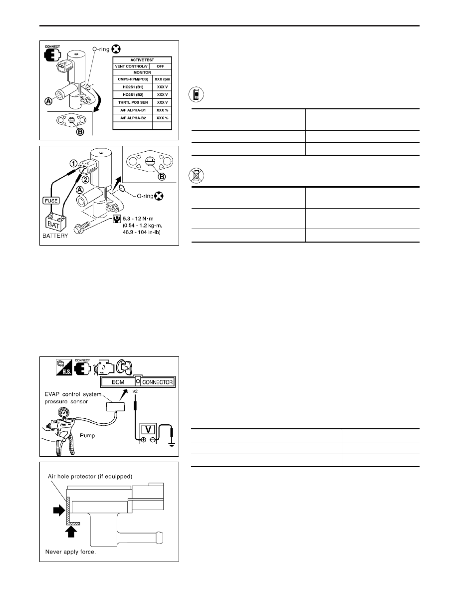
COMPONENT INSPECTION
EVAP canister vent control valve
Check air passage continuity.
Perform “VENT CONTROL/V” in “ACTIVE TEST” mode with
CONSULT-II.
Condition
VENT CONTROL/V
Air passage continuity
between
q
A
and
q
B
ON
No
OFF
Yes
------------------------------------------------------------------------------------------------------------------------------------------------------------------------------------------------------------------------------------------------------ OR ------------------------------------------------------------------------------------------------------------------------------------------------------------------------------------------------------------------------------------------------------
Condition
Air passage continuity
between
q
A
and
q
B
12V direct current supply between ter-
minals
q
1
and
q
2
No
No supply
Yes
If NG or operation takes more than 1 second, clean valve using air
blower or replace as necessary.
If the portion
q
B
is rusted, replace EVAP canister vent control
valve.
Make sure new O-ring is installed properly.
SEF357W
SEF799W
EVAP control system pressure sensor
1.
Remove EVAP control system pressure sensor with its har-
ness connector connected.
2.
Remove hose from EVAP control system pressure sensor.
3.
Turn ignition switch “ON”’.
4.
Use pump to apply vacuum and pressure to EVAP control
system pressure sensor as shown in figure.
5.
Check output voltage between ECM terminal
q
92
and ground.
Pressure (Relative to atmospheric pressure)
Voltage (V)
0 kPa (0 mmHg, 0 inHg)
3.0 - 3.6
−9.3 kPa (−70 mmHg, −2.76 inHg)
0.4 - 0.6
CAUTION:
I
Always calibrate the vacuum pump gauge when using it.
I
Do not apply below −20 kPa (−150 mmHg, −5.91 inHg) or
over 20 kPa (150 mmHg, 5.91 inHg) of pressure.
6.
If NG, replace EVAP control system pressure sensor.
I
Never apply force to the air hole protector of the sensor,
if equipped.
I
Discard any EVAP control system pressure sensor which
has been dropped from a height of more than 0.5 m (19.7
in) onto a hard surface such as a concrete floor; use a new
one.
TROUBLE DIAGNOSIS FOR DTC P1448
Evaporative Emission (EVAP) Canister Vent
Control Valve (Open) (Cont’d)
EC-468
Нет комментариевНе стесняйтесь поделиться с нами вашим ценным мнением.
Текст