Infiniti Q45 (FY33). Manual — part 176
SEF327R
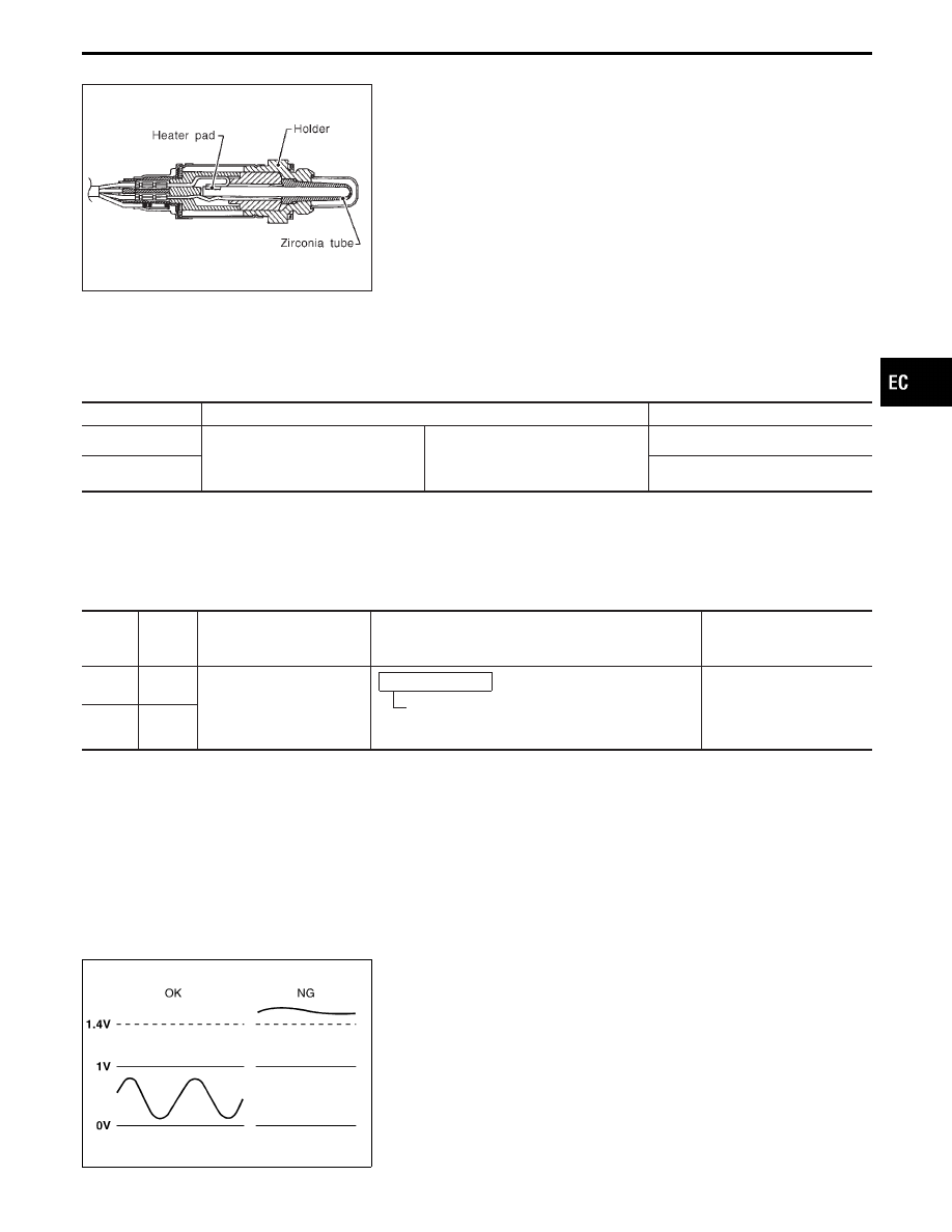
Heated Oxygen Sensor 2 (Rear) (P0140: Bank
1), (P0160: Bank 2) (High voltage)
COMPONENT DESCRIPTION
The heated oxygen sensor 2 (rear), after three way catalyst, moni-
tors the oxygen level in the exhaust gas on left and right bank.
Even if switching characteristics of the heated oxygen sensor 1
(front) are shifted, the air fuel ratio is controlled to stoichiometric,
by the signal from the each heated oxygen sensor 2 (rear).
This sensor is made of ceramic zirconia. The zirconia generates
voltage from approximately 1V in richer conditions to 0V in leaner
conditions.
Under normal conditions the heated oxygen sensor 2 (rear) is not
used for engine control operation.
CONSULT-II REFERENCE VALUE IN DATA MONITOR MODE
Specification data are reference values.
MONITOR ITEM
CONDITION
SPECIFICATION
HO2S2 (B1)
HO2S2 (B2)
I
Engine: After warming up
Revving engine from idle up to 2,000
rpm
0 - 0.3V
)
0.6 - 1.0V
HO2S2 MNTR (B1)
HO2S2 MNTR (B2)
LEAN
)
RICH
ECM TERMINALS AND REFERENCE VALUE
Specification data are reference values, and are measured between each terminal and ground.
CAUTION:
Do not use ECM ground terminals when measuring voltage. Doing so may result in damage to the
ECM’s transistor. Use a ground other than ECM terminals such as the body ground.
TER-
MINAL
NO.
WIRE
COLOR
ITEM
CONDITION
DATA
(DC voltage)
89 (B2)
W
Heated oxygen sensor 2
(rear)
Engine is running.
After warming up to normal operating tempera-
ture and revving engine from idle up to 2,000
rpm.
0 - Approximately 1.0V
90 (B1)
Y
SEF305UA
ON BOARD DIAGNOSIS LOGIC
The heated oxygen sensor 2 (rear) has a much longer switching
time between rich and lean than the heated oxygen sensor 1
(front). The oxygen storage capacity before the three way catalyst
causes the longer switching time. To judge the malfunctions of
heated oxygen sensor 2 (rear), ECM monitors whether the voltage
is unusually high during the various driving condition such as fuel-
cut.
GI
MA
EM
LC
FE
AT
PD
FA
RA
BR
ST
RS
BT
HA
EL
IDX
TROUBLE DIAGNOSIS FOR DTC P0140 (B1), P0160 (B2)
EC-233

Diagnostic Trouble
Code No.
Malfunction is detected when ...
Check Items
(Possible Cause)
P0140
0512
(Bank 1)
I
An excessively high voltage from the sensor is sent to ECM.
I
Harness or connectors
(The sensor circuit is open.)
I
Heated oxygen sensor 2 (rear)
P0160
0315
(Bank 2)
SEF270Y
SEF354WA
DIAGNOSTIC TROUBLE CODE CONFIRMATION
PROCEDURE
CAUTION:
Always drive vehicle at a safe speed.
NOTE:
If “DIAGNOSTIC TROUBLE CODE CONFIRMATION PROCE-
DURE” has been previously conducted, always turn ignition
switch “OFF” and wait at least 5 seconds before conducting
the next test.
1) Turn ignition switch “ON” and select “DATA MONITOR”
mode with CONSULT-II.
2) Start engine and drive vehicle at a speed of more than
70 km/h (43 MPH) for 2 consecutive minutes.
3) Maintain the following conditions for at least 5 consecu-
tive seconds.
CMPS-RPM (POS): 1,200 - 2,500 rpm
VHCL SPEED SE: 64 - 100 km/h (40 - 62 MPH)
B/FUEL SCHDL: 0.5 - 5.0 msec
COOLAN TEMP/S: More than 70°C (158°F)
Selector lever: Suitable position
4) Stop vehicle with engine running.
5) If 1st trip DTC is detected, go to “DIAGNOSTIC
PROCEDURE”, EC-237.
------------------------------------------------------------------------------------------------------------------------------------------------------------------------------------------------------------------------------------------------------ OR ------------------------------------------------------------------------------------------------------------------------------------------------------------------------------------------------------------------------------------------------------
OVERALL FUNCTION CHECK
Use this procedure to check the overall function of the heated oxy-
gen sensor 2 (rear) circuit. During this check, a 1st trip DTC might
not be confirmed.
1) Start engine and warm it up to normal operating tem-
perature.
2) Set voltmeter probes between ECM terminals
q
89
(B2),
q
90
(B1) (sensor signal) and ground.
3) Check the voltage when racing up to 4,000 rpm under
no load at least 10 times.
(depress and release accelerator pedal as soon as pos-
sible)
The voltage should be below 1.4V during this pro-
cedure.
4) If NG, go to “DIAGNOSTIC PROCEDURE”, EC-237.
TROUBLE DIAGNOSIS FOR DTC P0140 (B1), P0160 (B2)
Heated Oxygen Sensor 2 (Rear) (P0140: Bank
1), (P0160: Bank 2) (High voltage) (Cont’d)
EC-234

BANK 1
TEC787
GI
MA
EM
LC
FE
AT
PD
FA
RA
BR
ST
RS
BT
HA
EL
IDX
TROUBLE DIAGNOSIS FOR DTC P0140 (B1), P0160 (B2)
Heated Oxygen Sensor 2 (Rear) (P0140: Bank
1), (P0160: Bank 2) (High voltage) (Cont’d)
EC-235

BANK 2
TEC788
TROUBLE DIAGNOSIS FOR DTC P0140 (B1), P0160 (B2)
Heated Oxygen Sensor 2 (Rear) (P0140: Bank
1), (P0160: Bank 2) (High voltage) (Cont’d)
EC-236
Нет комментариевНе стесняйтесь поделиться с нами вашим ценным мнением.
Текст