Infiniti Q45 (FY33). Manual — part 177
SEF055TA
SEF377U
SEC032C
SEF398UA
SEF135T
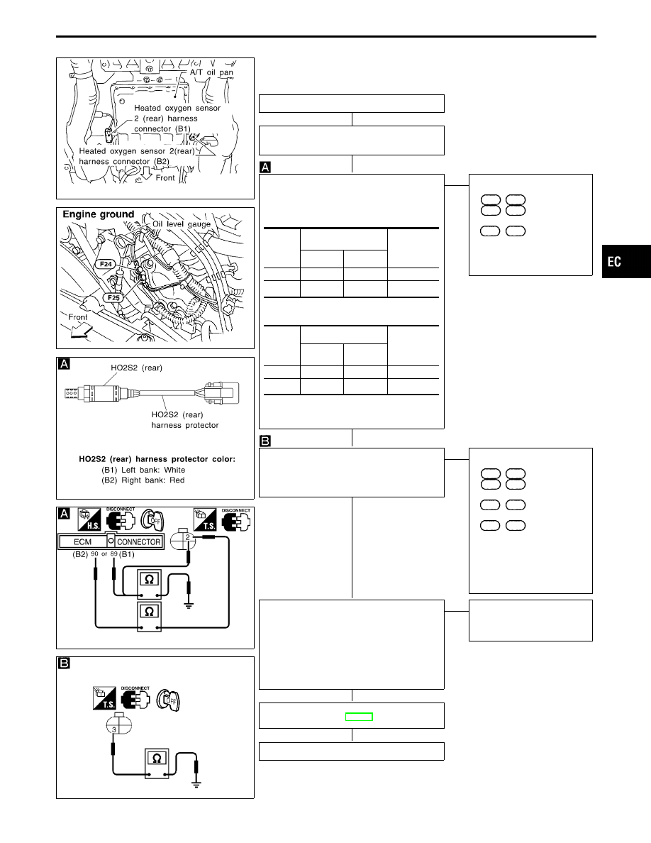
DIAGNOSTIC PROCEDURE
INSPECTION START
1. Turn ignition switch “OFF”.
2. Loosen and retighten engine ground screws.
CHECK INPUT SIGNAL CIRCUIT.
1. Disconnect heated oxygen sensor 2 (rear)
harness connector and ECM harness connec-
tor.
2. Check harness continuity between ECM and
sensor terminals.
Continuity should exist.
3. Check harness continuity between ECM sen-
sor or ground terminals.
Continuity should not exist.
If OK, check harness for short to ground and
short to power.
OK
E
NG
Check the following.
I
Harness connectors
F3
,
E12
(B1) or
F14
,
F131
(B2)
I
Harness connectors
E19
,
E102
(B1)
If NG, repair open circuit or
short to ground or short to
power in harness or connec-
tors.
CHECK GROUND CIRCUIT.
Check harness continuity between terminal
q
3
and engine ground.
Continuity should exist.
If OK, check harness for short to power.
OK
E
NG
Check the following.
I
Harness connectors
F3
,
E12
(B1) or
F14
,
F131
(B2)
I
Harness connectors
E19
,
E102
(B1)
I
Harness connectors
F62
,
F61
I
Harness for open or short
between heated oxygen sen-
sor 2 (rear) and engine
ground
If NG, repair open circuit or
short to power in harness or
connectors.
CHECK COMPONENT
[Heated oxygen sensor 2 (rear)].
1. Turn ignition switch “OFF”.
2. Disconnect sensor harness connector and
check for water.
Water should not exist.
If OK, go to step 3.
3. Check heated oxygen sensor 2 (rear).
Refer to “COMPONENT INSPECTION” on next
page.
OK
E
NG
Repair or replace harness
and/or connectors or replace
corresponding heated oxygen
sensor.
Perform “TROUBLE DIAGNOSIS FOR INTER-
MITTENT INCIDENT”, EC-117.
OK
INSPECTION END
DTC
Terminals
Bank
(Harness
protector
color)
ECM
Sensor
P0140
90
2
(B1) (White)
P0160
89
2
(B2) (Red)
DTC
Terminals
Bank
(Harness
protector
color)
ECM or
sensor
Ground
P0140
90 or 2
Ground
(B1) (White)
P0160
89 or 2
Ground
(B2) (Red)
GI
MA
EM
LC
FE
AT
PD
FA
RA
BR
ST
RS
BT
HA
EL
IDX
TROUBLE DIAGNOSIS FOR DTC P0140 (B1), P0160 (B2)
Heated Oxygen Sensor 2 (Rear) (P0140: Bank
1), (P0160: Bank 2) (High voltage) (Cont’d)
H
H
H
H
H
H
EC-237
SEC033C
SEF354WA
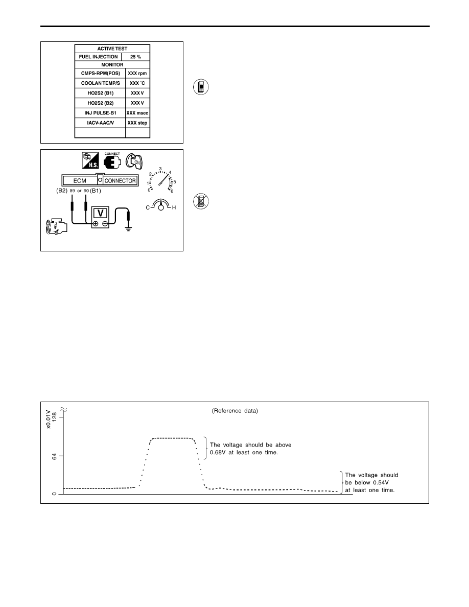
COMPONENT INSPECTION
Heated oxygen sensor 2 (rear)
1) Start engine and drive vehicle at a speed of more than
70 km/h (43 MPH) for 2 consecutive minutes.
2) Stop vehicle with engine running.
3) Select “FUEL INJECTION” in “ACTIVE TEST” mode,
and select “HO2S2 (B1) (B2)” as the monitor item with
CONSULT-II.
4) Check “HO2S2 (B1) (B2)” at idle speed when adjusting
“FUEL INJECTION” to ±25%.
“HO2S2 (B1) (B2)” should be above 0.48V at least
once when the “FUEL INJECTION” is +25%.
“HO2S2 (B1) (B2)” should be below 0.43V at least
once when the “FUEL INJECTION” is −25%.
------------------------------------------------------------------------------------------------------------------------------------------------------------------------------------------------------------------------------------------------------ OR ------------------------------------------------------------------------------------------------------------------------------------------------------------------------------------------------------------------------------------------------------
1) Start engine and drive vehicle at a speed of more than
70 km/h (43 MPH) for 2 consecutive minutes.
2) Stop vehicle with engine running.
3) Set voltmeter probes between ECM terminals
q
89
(B2),
q
90
(B1) (sensor signal) and ground.
4) Check the voltage when racing up to 4,000 rpm under
no load at least 10 times.
(depress and release accelerator pedal as soon as pos-
sible)
The voltage should be above 0.48V at least once.
If the voltage is above 0.48V at step 4, step 5 is not
necessary.
5) Keep vehicle at idling for 10 minutes, then check the
voltage. Or check the voltage when coasting from 80
km/h (50 MPH) in D position with “OD” OFF.
The voltage should be below 0.43V at least once.
CAUTION:
I
Discard any heated oxygen sensor which has been
dropped from a height of more than 0.5 m (19.7 in) onto a
hard surface such as a concrete floor; use a new one.
I
Before installing new oxygen sensor, clean exhaust sys-
tem threads using Oxygen Sensor Thread Cleaner tool
J-43897-18 or J-43897-12 and approved anti-seize lubri-
cant.
SEF244Y
TROUBLE DIAGNOSIS FOR DTC P0140 (B1), P0160 (B2)
Heated Oxygen Sensor 2 (Rear) (P0140: Bank
1), (P0160: Bank 2) (High voltage) (Cont’d)
EC-238

Heated Oxygen Sensor 2 Heaters (Rear)
(P0141: Bank 1), (P0161: Bank 2)
SYSTEM DESCRIPTION
Camshaft position sensor
E
Engine speed
ECM
E
Heated
oxygen
sensor 2
heater
(rear)
Mass air flow sensor
E
Amount of intake air
The ECM performs ON/OFF control of the heated
oxygen sensor 2 heater (rear) corresponding to the
engine speed.
OPERATION
Engine speed rpm
Heated oxygen sensor 2
heater (rear)
Ignition switch “ON” (Engine
stopped)
OFF
At idle [after driving for 2 min-
utes at a speed of more than
70 km/h (43 MPH)]
ON
CONSULT-II REFERENCE VALUE IN DATA MONITOR MODE
Specification data are reference values.
MONITOR ITEM
CONDITION
SPECIFICATION
HO2S2 HTR (B1)
HO2S2 HTR (B2)
I
Engine speed: At idle [after driving for 2 minutes at a speed of more than 70
km/h (43 MPH)]
ON
I
Engine speed: Above 3,600 rpm
I
Ignition “ON” with engine stopped
OFF
ECM TERMINALS AND REFERENCE VALUE
Specification data are reference values, and are measured between each terminal and ground.
CAUTION:
Do not use ECM ground terminals when measuring voltage. Doing so may result in damage to the
ECM’s transistor. Use a ground other than ECM terminals such as the body ground.
TER-
MINAL
NO.
WIRE
COLOR
ITEM
CONDITION
DATA
(DC voltage)
18
19
Y/R
L
Heated oxygen sensor 2
heater (rear) (B1)
Heated oxygen sensor 2
heater (rear) (B2)
Engine is running.
At idle [after driving 2 minutes at 70 km/h (43
MPH) or more]
0 - 0.5V
Ignition switch “ON”
Engine stopped
Engine is running.
Engine speed is above 3,600 rpm.
BATTERY VOLTAGE
(11 - 14V)
GI
MA
EM
LC
FE
AT
PD
FA
RA
BR
ST
RS
BT
HA
EL
IDX
TROUBLE DIAGNOSIS FOR DTC P0141 (B1), P0161 (B2)
EC-239
ON BOARD DIAGNOSIS LOGIC
Diagnostic Trouble
Code No.
Malfunction is detected when .
Check Items
(Possible Cause)
P0141
0902
(B1)
I
The current amperage in the heated oxygen sensor
2 heater (rear) circuit is out of the normal range.
[The improper voltage drop signal is sent to ECM
through the heated oxygen sensor 2 heater (rear).]
I
Harness or connectors
[The heated oxygen sensor 2 heater (rear) circuit is
open or shorted.]
I
Heated oxygen sensor 2 heater (rear)
P0161
1002
(B2)
SEF261Y
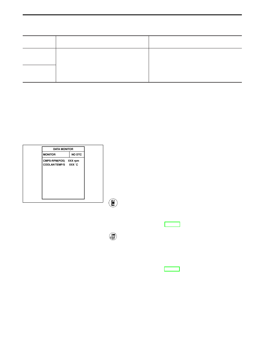
DIAGNOSTIC TROUBLE CODE CONFIRMATION
PROCEDURE
NOTE:
If “DIAGNOSTIC TROUBLE CODE CONFIRMATION PROCE-
DURE” has been previously conducted, always turn ignition
switch “OFF” and wait at least 5 seconds before conducting
the next test.
TESTING CONDITION:
Before performing the following procedure, confirm that bat-
tery voltage is more than 10.5V.
1) Turn ignition switch “ON” and select “DATA MONITOR”
mode with CONSULT-II.
2) Start engine and drive vehicle at a speed of more than
70 km/h (43 MPH) for 2 consecutive minutes.
3) If 1st trip DTC is detected, go to “DIAGNOSTIC
PROCEDURE”, EC-243.
------------------------------------------------------------------------------------------------------------------------------------------------------------------------------------------------------------------------------------------------------ OR ------------------------------------------------------------------------------------------------------------------------------------------------------------------------------------------------------------------------------------------------------
1) Start engine and drive vehicle at a speed of more than
70 km/h (43 MPH) for 2 consecutive minutes.
2) Turn ignition switch “OFF” and wait at least 5 seconds.
3) Start engine and drive vehicle at a speed of more than
70 km/h (43 MPH) for 2 consecutive minutes.
4) Select “MODE 3” with GST.
5) If
DTC
is
detected,
go
to
“DIAGNOSTIC
PROCEDURE”, EC-243.
When using GST, “DIAGNOSTIC TROUBLE CODE CONFIRMA-
TION PROCEDURE” should be performed twice as much as
when using CONSULT-II because GST cannot display MODE 7
(1st trip DTC) concerning this diagnosis. Therefore, using
CONSULT-II is recommended.
TROUBLE DIAGNOSIS FOR DTC P0141 (B1), P0161 (B2)
Heated Oxygen Sensor 2 Heaters (Rear)
(P0141: Bank 1), (P0161: Bank 2) (Cont’d)
EC-240
Нет комментариевНе стесняйтесь поделиться с нами вашим ценным мнением.
Текст