Infiniti Q45 (FY33). Manual — part 134
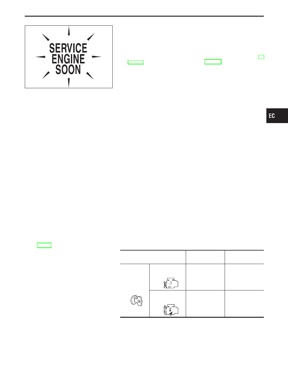
SEF217U
Malfunction Indicator Lamp (MIL)
The malfunction indicator lamp is located on the instrument panel.
1.
The malfunction indicator lamp will light up when the ignition
switch is turned ON without the engine running. This is a bulb
check.
I
If the malfunction indicator lamp does not light up, refer to EL
section WARNING LAMPS or see EC-535.
2.
When the engine is started, the malfunction indicator lamp
should go off.
If the lamp remains on, the on board diagnostic system has
detected an engine system malfunction.
ON BOARD DIAGNOSTIC SYSTEM FUNCTION
The on board diagnostic system has the following four functions.
Diagnostic Test Mode I
1. BULB CHECK
: This function checks the bulb for damage (blown, open circuit, etc.) of
the malfunction indicator lamp.
If the MIL does not come on, check MIL circuit and ECM test mode.
(See next page.)
2. MALFUNCTION
WARNING
: This is a usual driving condition. When a malfunction is detected twice
in two consecutive driving cycles (2 trip detection logic), the MIL will
light up to inform the driver that a malfunction has been detected.
The following malfunctions will light up or blink the MIL in the 1st trip.
I
“Misfire (possible three way catalyst damage)”
I
“Closed loop control”
I
Fail-safe mode
Diagnostic Test Mode II
3. SELF-DIAGNOSTIC
RESULTS
: This function allows DTCs and 1st trip DTCs to be read.
4. HEATED OXYGEN
SENSORS 1 MONI-
TOR (FRONT)
: This function allows the fuel mixture condition (lean or rich), monitored
by heated oxygen sensors 1 monitor (front), to be read.
MIL Flashing without DTC
If the ECM is in Diagnostic Test Mode II, the MIL may flash when the engine is running. In this case, check
ECM test mode selector following “HOW TO SWITCH DIAGNOSTIC TEST MODES” on next page.
How to switch the diagnostic test (function) modes and details of the above functions are described later. (See
page EC-66.)
Condition
Diagnostic
Test Mode I
Diagnostic
Test Mode II
Ignition switch
in “ON” posi-
tion
Engine
stopped
BULB CHECK
SELF-DIAGNOSTIC
RESULTS
Engine
running
MALFUNCTION
WARNING
HEATED OXYGEN
SENSOR 1 MONI-
TOR (FRONT)
GI
MA
EM
LC
FE
AT
PD
FA
RA
BR
ST
RS
BT
HA
EL
IDX
ON BOARD DIAGNOSTIC SYSTEM DESCRIPTION
EC-65
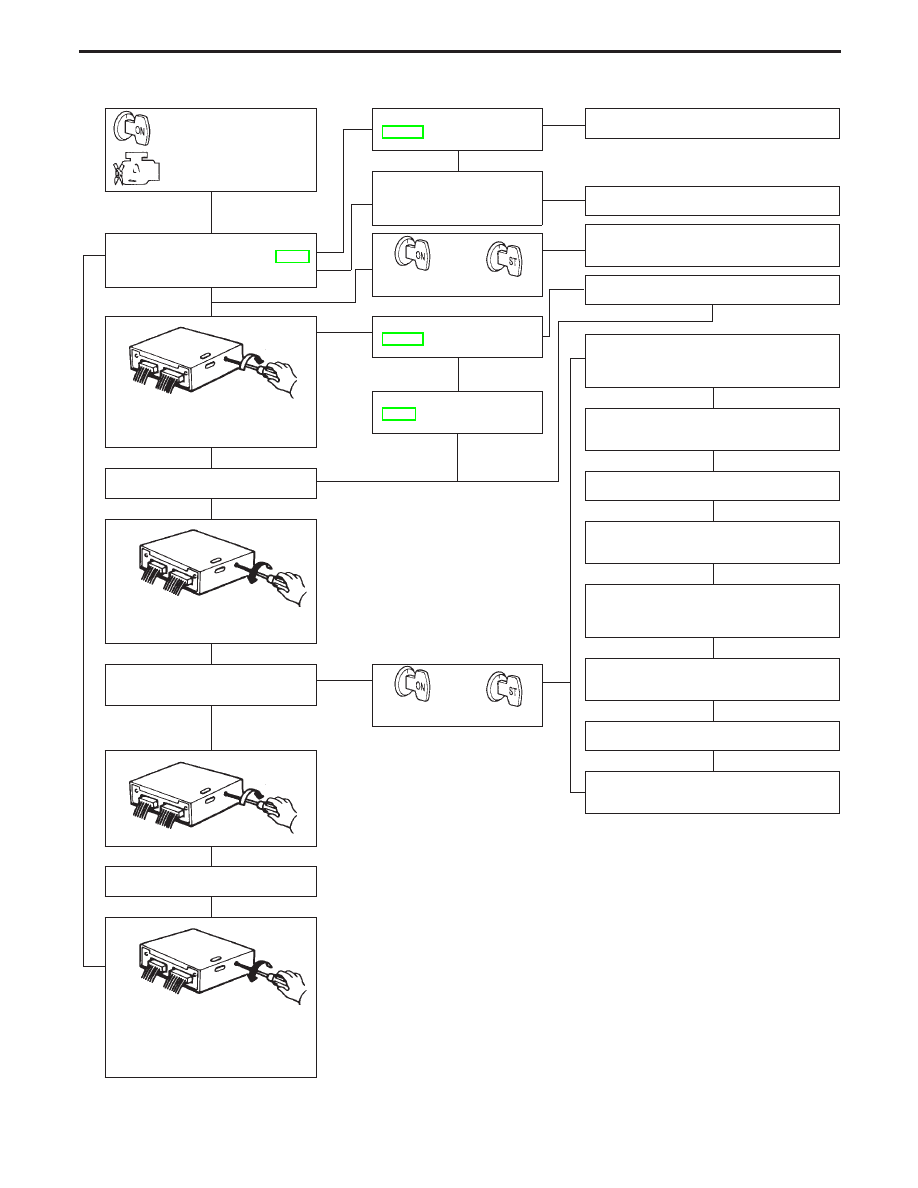
HOW TO SWITCH DIAGNOSTIC TEST MODES
Turn ignition switch
“ON”. (Do not start
engine.)
Check MIL circuit. (See
EC-535.)
OK
E
NG
Repair harness or connector
Check whether ECM test
mode selector can be
turned counterclockwise.
E
No
E
Mode I — MALFUNCTION INDICA-
TOR LAMP CHECK. Refer to EC-65.
MIL should come on.
OK
E
NG
F
Yes
G
Start engine.
E
E
(Turn diagnostic test mode selector
on ECM fully clockwise.)
MIL should come off.
OK
E
NG
Check MIL circuit. (See
EC-535.)
OK
E
NG
Check ECM fail-safe. (See
EC-98.)
OK
F
Wait at least 2 seconds.
F
(Turn diagnostic test mode selector
fully counterclockwise.)
DIAGNOSTIC TEST MODE II
— SELF-DIAGNOSTIC RESULTS
(ERASING ECM
MEMORY.)
E
G
Start engine.
Wait at least 2 seconds.
If the selector is turned fully
counterclockwise at this time,
the emission-related diagnostic
information will be erased from
the backup memory in the ECM.
Repair or replace ECM test mode selector.
Diagnostic Test Mode I
— MALFUNCTION WARNING
Repair harness or connectors.
OK
Diagnostic Test Mode II*1
— HEATED OXYGEN SENSOR 1 MONI-
TOR (FRONT) (B1)
Turn diagnostic test mode selector on ECM
fully clockwise.
Wait at least 2 seconds.
Turn diagnostic test mode selector on ECM
fully counterclockwise.
Diagnostic Test Mode II
— HEATED OXYGEN SENSOR 1 MONI-
TOR (FRONT) (B2)
Turn diagnostic test mode selector on ECM
fully clockwise.
Wait at least 2 seconds.
E
Turn diagnostic test mode selector on ECM
fully counterclockwise.
*1: If the battery is weak, heated oxygen sensors 1 monitor (front) may not func-
tion properly. Use this function after fully charging battery.
The following emission-related diagnostic information is cleared
when the ECM memory is erased.
1. Diagnostic trouble codes
2. 1st trip diagnostic trouble codes
3. Freeze frame data
4. 1st trip freeze frame data
5. System readiness test (SRT) codes
6. Test values
7. Others
I
Switching the modes is not possible when the engine is
running.
I
When ignition switch is turned off during diagnosis,
power to ECM will drop after approx. 5 seconds.
The diagnosis will automatically return to Diagnostic Test
Mode I.
I
Turn back diagnostic test mode selector to the fully coun-
terclockwise position whenever vehicle is in use.
ON BOARD DIAGNOSTIC SYSTEM DESCRIPTION
Malfunction Indicator Lamp (MIL) (Cont’d)
H
H
H
H
H
H
H
H
H
H
H
H
H
H
H
H
H
EC-66
DIAGNOSTIC TEST MODE I—BULB CHECK
In this mode, the MALFUNCTION INDICATOR LAMP on the instrument panel should stay ON. If it remains
OFF, check the bulb. (See the WARNING LAMPS in the EL section. Or see EC-535.)
DIAGNOSTIC TEST MODE I—MALFUNCTION WARNING
MALFUNCTION
INDICATOR LAMP
Condition
ON
When the malfunction is detected or the ECM’s CPU is malfunctioning.
OFF
No malfunction
I
These Diagnostic Trouble Code Numbers are clarified in Diagnostic Test Mode II (SELF-DIAGNOSTIC
RESULTS).
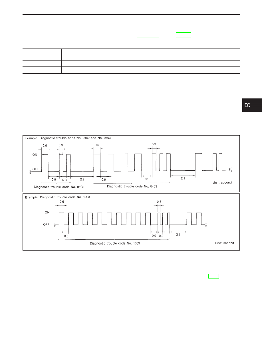
DIAGNOSTIC TEST MODE II—SELF-DIAGNOSTIC RESULTS
In this mode, the DTC and 1st trip DTC are indicated by the number of blinks of the MALFUNCTION INDI-
CATOR LAMP as shown below.
The DTC and 1st trip DTC are displayed at the same time. If the MIL does not illuminate in diagnostic test
mode 1 (Malfunction warning), all displayed items are 1st trip DTC’s. If only one code is displayed when the
MIL illuminates in diagnostic test mode II (SELF-DIAGNOSTIC RESULTS), it is a DTC; if two or more codes
are displayed, they may be either DTC’s or 1st trip DTC’s. DTC No. is same as that of 1st trip DTC. These
unidentified codes can be identified by using the consult or GST. A DTC will be used as an example for how
to read a code.
SEF298Q
SEF162PA
Long (0.6 second) blinking indicates the two LH digits of number and short (0.3 second) blinking indicates the
two RH digits of number. For example, the malfunction indicator lamp blinks 10 times for 6 seconds (0.6 sec
x 10 times) and then it blinks three times for about 1 second (0.3 sec x 3 times). This indicates the DTC “1003”
and refers to the malfunction of the park/neutral position switch.
In this way, all the detected malfunctions are classified by their diagnostic trouble code numbers. The DTC
“0505” refers to no malfunction. (See DIAGNOSTIC TROUBLE CODE INDEX, refer to page EC-4.)
HOW TO ERASE DIAGNOSTIC TEST MODE II (Self-diagnostic results)
The diagnostic trouble code can be erased from the backup memory in the ECM when the diagnostic test mode
is changed from Diagnostic Test Mode II to Diagnostic Test Mode I. (Refer to “HOW TO SWITCH DIAGNOS-
TIC TEST MODES”.)
I
If the battery terminal is disconnected, the diagnostic trouble code will be lost from the backup
memory within 24 hours.
I
Be careful not to erase the stored memory before starting trouble diagnoses.
GI
MA
EM
LC
FE
AT
PD
FA
RA
BR
ST
RS
BT
HA
EL
IDX
ON BOARD DIAGNOSTIC SYSTEM DESCRIPTION
Malfunction Indicator Lamp (MIL) (Cont’d)
EC-67
DIAGNOSTIC TEST MODE II—HEATED OXYGEN SENSOR 1 MONITOR (FRONT)
In this mode, the MALFUNCTION INDICATOR LAMP displays the condition of the fuel mixture (lean or rich)
which is monitored by the heated oxygen sensors 1 (front).
MALFUNCTION INDICATOR LAMP
Fuel mixture condition in the exhaust gas
Air fuel ratio feedback control
condition
ON
Lean
Closed loop control
OFF
Rich
*Remains ON or OFF
Any condition
Open loop control
*: Maintains conditions just before switching to open loop.
To check the heated oxygen sensors 1 (front) function, start engine in the Diagnostic Test Mode II and warm
it up until engine coolant temperature indicator points to the middle of the gauge.
Next run engine at about 2,000 rpm for about 2 minutes under no-load conditions. Then make sure that the
MALFUNCTION INDICATOR LAMP comes ON more than 5 times every 10 seconds when measured at 2,000
rpm under no-load.
If the battery is weak, heated oxygen sensors 1 monitor (front) may not function properly. Use this
function after fully charging battery.
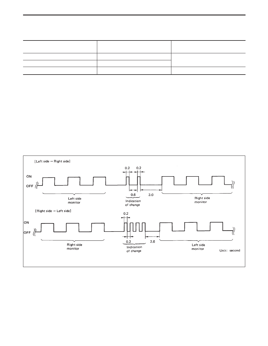
How to switch monitored sensor from left bank to right bank or vice versa
I
The following procedure should be performed while the engine is running.
1. Turn diagnostic test mode selector on ECM fully clockwise.
2. Wait at least 2 seconds.
3. Turn diagnostic test mode selector on ECM fully counterclockwise.
SEF134M
ON BOARD DIAGNOSTIC SYSTEM DESCRIPTION
Malfunction Indicator Lamp (MIL) (Cont’d)
EC-68
Нет комментариевНе стесняйтесь поделиться с нами вашим ценным мнением.
Текст