Infiniti Q45 (FY33). Manual — part 132
I
The time required for each diagnosis varies with road sur-
face conditions, weather, altitude, individual driving habits,
etc.
Zone A refers to the range where the time required, for the
diagnosis under normal conditions*, is the shortest. Zone B
refers to the range where the diagnosis can still be per-
formed if the diagnosis is not completed within zone A.
*: Normal conditions refer to the following:
— Sea level
— Flat road
— Ambient temperature: 20 - 30°C (68 - 86°F)
— Diagnosis is performed as quickly as possible under nor-
mal conditions.
Under different conditions [For example: ambient tempera-
ture is other than 20 - 30°C (68 - 86°F)], diagnosis may
also be performed.
Pattern 1:
I
The engine is started at the engine coolant tem-
perature of −10 to 35°C (14 to 95°F) (where the
voltage between the ECM terminal
q
67
and
ground is 3.0 - 4.3 V.)
I
The engine must be operated at idle speed until
the engine coolant temperature is greater than
70°C (158°F) (where the voltage between the
ECM terminal
q
67
and ground is lower than 1.4 V.)
I
The engine is started at a fuel tank temperature
warmer than 0°C (32°F) (where the voltage
between the ECM terminal
q
91
and ground is less
than 4.1V).
Pattern 2:
I
When steady-state driving is performed again
even after it is interrupted, each diagnosis can
be conducted. In this case, the time required for
diagnosis may be extended.
Pattern 3:
I
The driving pattern outlined in *2 must be
repeated at least 3 times.
Pattern 4:
I
Tests are performed after the engine has been
operated for at least 17 minutes.
I
The accelerator pedal must be held very steady
during steady-state driving.
I
If the accelerator pedal is moved, the test must
be conducted all over again.
*1: Depress the accelerator pedal until vehicle speed is 90
km/h (56 MPH), then release the accelerator pedal and
keep it released for more than 10 seconds. Depress the
accelerator pedal until vehicle speed is 90 km/h (56 MPH)
again.
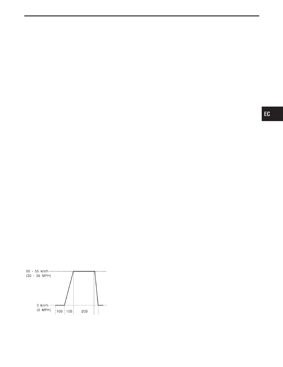
*2: Operate the vehicle in the following driving pattern.
1) Decelerate vehicle to 0 km/h (0 MPH) and let it idle.
2) Repeat driving pattern shown below at least 10 times.
I
During acceleration, hold the accelerator pedal
as steady as possible.
3) Repeat steps and 2 until the EGR system SRT is set.
SEF414S
*3: Checking the vehicle speed with GST is advised.
Suggested transmission gear position
Set the selector lever in the “D” position with “OD”
ON.
Suggested maximum speed in each gear
Downshift to a lower gear if the engine is not running
smoothly, or if you need to accelerate.
Do not exceed the maximum suggested speed
(shown below) in any gear. For level road driving,
use the highest gear suggested for that speed.
Always observe posted speed limits, and drive
according to the road conditions, which will ensure
safe operation. Do not over-rev the engine when
shifting to a lower gear as it may cause engine dam-
age or loss of vehicle control.
Gear
km/h (MPH)
1st
50 (30)
2nd
95 (60)
3rd
145 (90)
4th
—
5th
—
GI
MA
EM
LC
FE
AT
PD
FA
RA
BR
ST
RS
BT
HA
EL
IDX
ON BOARD DIAGNOSTIC SYSTEM DESCRIPTION
Emission-related Diagnostic Information
(Cont’d)
EC-57

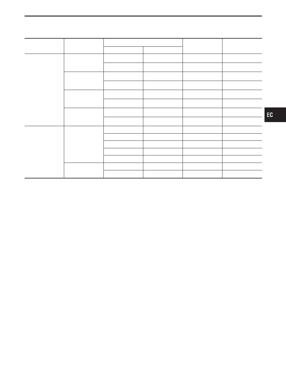
TEST VALUE AND TEST LIMIT (GST only — not applicable to CONSULT-II)
The following is the information specified in Mode 6 of SAE J1979.
The test value is a parameter used to determine whether a system/circuit diagnostic test is “OK” or “NG” while
being monitored by ECM during self-diagnosis. The test limit is a reference value which is specified as the
maximum or minimum value and is compared with the test value being monitored.
Items for which these data (test value and test limit) are displayed are the same as SRT code items (14 test
items).
These data (test limit) are specified by Test ID (TID) and Component ID (CID). These data can be displayed
on the GST screen.
X: Applicable
—: Not applicable
SRT item
Self-diagnostic test
item
Test value
Test limit
Application
TID
CID
CATALYST
Three way catalyst
function
(Left bank)
01H
01H
Max.
X
Three way catalyst
function
(Right bank)
03H
02H
Max.
X
EVAP SYSTEM
EVAP control sys-
tem
(Small leak)
05H
03H
Max.
X
EVAP control sys-
tem purge flow
monitoring
06H
83H
Min.
X
O2 SENSOR
Heated oxygen sen-
sor 1 (front) (B1)
09H
04H
Max.
X
0AH
84H
Min.
X
0BH
04H
Max.
X
0CH
04H
Max.
X
0DH
04H
Max.
X
Heated oxygen sen-
sor 1 (front) (B2)
11H
05H
Max.
X
12H
85H
Min.
X
13H
05H
Max.
X
14H
05H
Max.
X
15H
05H
Max.
X
Heated oxygen sen-
sor 2 (rear) (B1)
19H
86H
Min.
X
1AH
86H
Min.
X
1BH
06H
Max.
X
1CH
06H
Max.
X
Heated oxygen sen-
sor 2 (rear) (B2)
21H
87H
Min.
X
22H
87H
Min.
X
23H
07H
Max.
X
24H
07H
Max.
X
ON BOARD DIAGNOSTIC SYSTEM DESCRIPTION
Emission-related Diagnostic Information
(Cont’d)
EC-58
SRT item
Self-diagnostic test
item
Test value
Test limit
Application
TID
CID
O2 SENSOR
HEATER
Heated oxygen sen-
sor 1 heater (front)
(B1)
29H
08H
Max.
X
2AH
88H
Min.
X
Heated oxygen sen-
sor 1 heater (front)
(B2)
2BH
09H
Max.
X
2CH
89H
Min.
X
Heated oxygen sen-
sor 2 heater (rear)
(B1)
2DH
0AH
Max.
X
2EH
8AH
Min.
X
Heated oxygen sen-
sor 2 heater (rear)
(B2)
2FH
0BH
Max.
X
30H
8BH
Min.
X
EGR SYSTEM
EGR function
31H
8CH
Min.
X
32H
8CH
Min.
X
33H
8CH
Min.
X
34H
8CH
Min.
X
35H
0CH
Max.
X
EGRC-BPT valve
function
36H
0CH
Max.
X
37H
8CH
Min.
X
GI
MA
EM
LC
FE
AT
PD
FA
RA
BR
ST
RS
BT
HA
EL
IDX
ON BOARD DIAGNOSTIC SYSTEM DESCRIPTION
Emission-related Diagnostic Information
(Cont’d)
EC-59

EMISSION-RELATED DIAGNOSTIC INFORMATION ITEMS
X: Applicable
—: Not applicable
Items
(CONSULT-II screen terms)
DTC*4
SRT code
Test value/
Test limit
(GST only)
1st trip DTC*4
Reference page
CONSULT-II
GST*2
ECM*1
NO DTC IS DETECTED,
FURTHER TESTING
MAY BE REQUIRED.
P0000
0505
—
—
—
—
MAF SEN/CIRCUIT
P0100
0102
—
—
X
ABSL PRES SEN/CIRC
P0105
0803
—
—
X
AIR TEMP SEN/CIRC
P0110
0401
—
—
X
COOLANT T SEN/CIRC
P0115
0103
—
—
X
THRTL POS SEN/CIRC
P0120
0403
—
—
X
*COOLAN T SEN/CIRC
P0125
0908
—
—
X
HO2S1 (B1)
P0130
0303
X
X
X*3
HO2S1 (B1)
P0131
0411
X
X
X*3
HO2S1 (B1)
P0132
0410
X
X
X*3
HO2S1 (B1)
P0133
0409
X
X
X*3
HO2S1 (B1)
P0134
0412
X
X
X*3
HO2S1 HTR (B1)
P0135
0901
X
X
X*3
HO2S2 (B1)
P0137
0511
X
X
X*3
HO2S2 (B1)
P0138
0510
X
X
X*3
HO2S2 (B1)
P0139
0707
X
X
X*3
HO2S2 (B1)
P0140
0512
X
X
X*3
HO2S2 HTR (B1)
P0141
0902
X
X
X*3
HO2S1 (B2)
P0150
0503
X
X
X*3
HO2S1 (B2)
P0151
0415
X
X
X*3
HO2S1 (B2)
P0152
0414
X
X
X*3
HO2S1 (B2)
P0153
0413
X
X
X*3
HO2S1 (B2)
P0154
0509
X
X
X*3
HO2S1 HTR (B2)
P0155
1001
X
X
X*3
HO2S2 (B2)
P0157
0314
X
X
X*3
HO2S2 (B2)
P0158
0313
X
X
X*3
HO2S2 (B2)
P0159
0708
X
X
X*3
HO2S2 (B2)
P0160
0315
X
X
X*3
HO2S2 HTR (B2)
P0161
1002
X
X
X*3
FUEL SYS LEAN/BK1
P0171
0115
—
—
X
FUEL SYS RICH/BK1
P0172
0114
—
—
X
FUEL SYS LEAN/BK2
P0174
0210
—
—
X
FUEL SYS RICH/BK2
P0175
0209
—
—
X
FUEL TEMP SEN/CIRC
P0180
0402
—
—
X
MULTI CYL MISFIRE
P0300
0701
—
—
X
CYL 1 MISFIRE
P0301
0608
—
—
X
CYL 2 MISFIRE
P0302
0607
—
—
X
*1: In Diagnostic Test Mode II (Self-diagnostic results). These numbers are controlled by NISSAN.
*2: These numbers are prescribed by SAE J2012.
*3: These are not displayed with GST.
*4: 1st trip DTC No. is the same as DTC No.
ON BOARD DIAGNOSTIC SYSTEM DESCRIPTION
Emission-related Diagnostic Information
(Cont’d)
EC-60
Нет комментариевНе стесняйтесь поделиться с нами вашим ценным мнением.
Текст