Infiniti Q45 (FY33). Manual — part 429
SFA336B
I
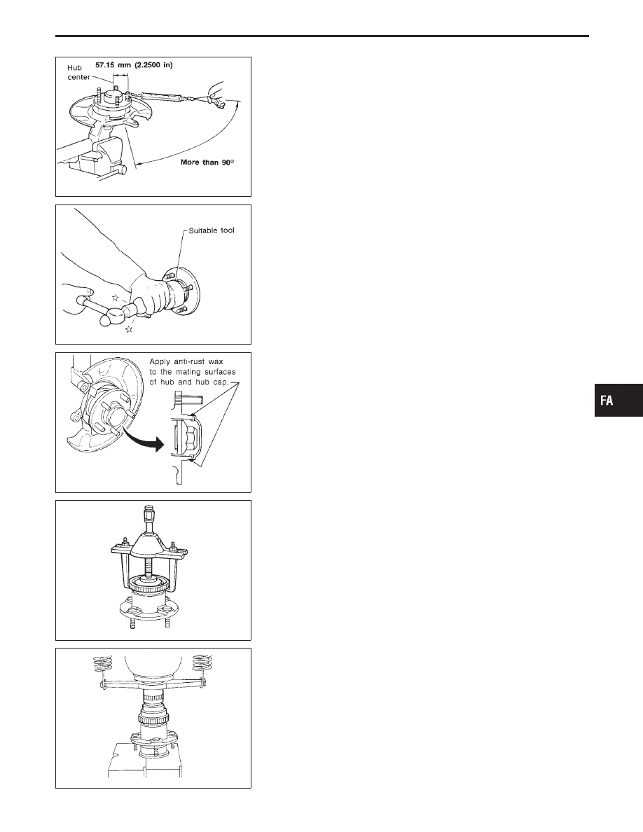
Turn wheel hub several times in both directions to seat wheel
bearing correctly.
I
Attach spring balance to wheel hub bolt (as shown at left) and
pull it at a speed of 10 rpm to measure rotation torque.
Rotation torque:
0.25 - 2.11 N
⋅
m (2.5 - 21.5 kg-cm, 2.2 - 18.7 in-lb)
Spring balance indication:
3.9 - 37.2 N (0.4 - 3.8 kg, 0.9 - 8.4 lb)
If bearing preload does not meet the specification, replace
wheel bearing assembly.
SFA337B
I
Clinch lock nut using standard screwdriver and install hub cap
using a suitable tool.
Do not reuse hub cap. When installing, replace it with a new
one.
SFA713B
I
Apply anti-rust wax to the mating surfaces of hub and hub cap.
SFA595B
ABS Sensor Rotor
REMOVAL
Remove ABS sensor rotor.
SFA596B
INSTALLATION
Press-fit ABS sensor rotor.
GI
MA
EM
LC
EC
FE
AT
PD
RA
BR
ST
RS
BT
HA
EL
IDX
FRONT AXLE
Wheel Hub and Knuckle (Cont’d)
FA-15
SFA793BA
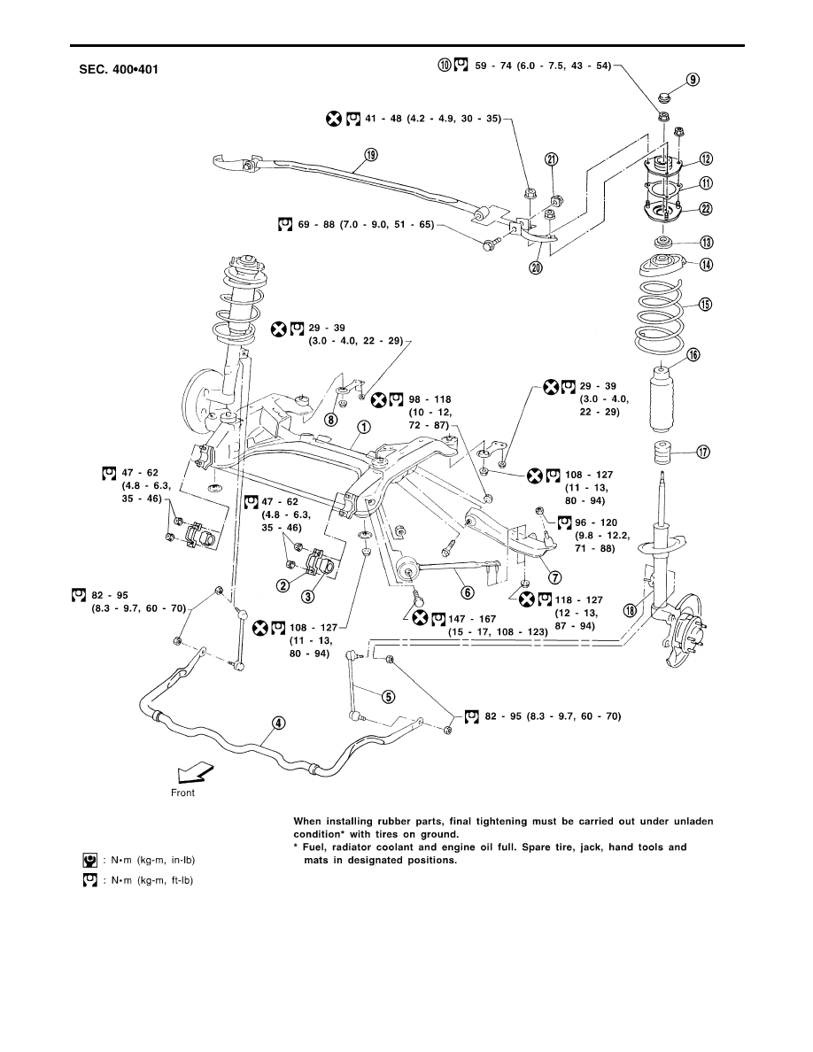
q
1
Front suspension member
q
2
Stabilizer bar clamp
q
3
Bushing
q
4
Stabilizer bar
q
5
Stabilizer connecting rod
q
6
Tension rod
q
7
Transverse link
q
8
Member stay
q
9
Cap
q
10
Lock nut
q
11
Gasket
q
12
Strut mounting insulator
q
13
Strut mounting bearing
q
14
Spring upper seat
q
15
Coil spring
q
16
Dust cover
q
17
Bound bumper
q
18
Strut assembly
q
19
Front tower bar
q
20
Bracket
q
21
Plate nut
q
22
Strut mounting bracket
FRONT SUSPENSION
FA-16
SFA328B
Coil Spring and Strut Assembly
NOTE:
For removal and installation procedures of active damper sus-
pension-related parts, refer to “Removal and Installation”,
“ACTIVE DAMPER SUSPENSION”, FA-27.
REMOVAL AND INSTALLATION
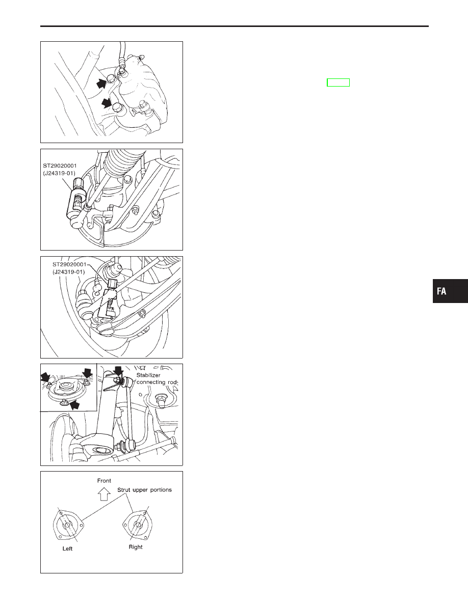
I
Remove brake caliper assembly and rotor.
Brake hose need not be disconnected from brake caliper. Be
careful not to depress brake pedal, or piston will pop out.
Do not pull or twist brake hose.
SFA794BA
I
Remove tie-rod ball joint and lower ball joint with Tool.
SFA797B
SFA341B
I
Remove stabilizer connecting rod upper nut, separate strut
assembly and stabilizer connecting rod.
I
Remove strut assembly upper nuts.
SFA342B
I
To install, reverse above removal procedures.
Installation position of upper end of strut is shown at left.
GI
MA
EM
LC
EC
FE
AT
PD
RA
BR
ST
RS
BT
HA
EL
IDX
FRONT SUSPENSION
FA-17
SFA261B
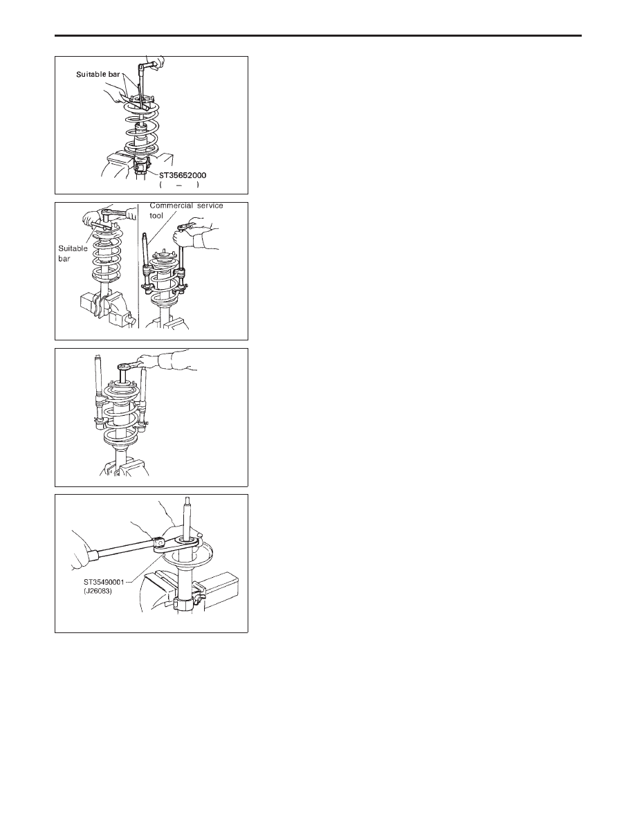
DISASSEMBLY
1.
Set strut assembly on vice with attachment, then loosen pis-
ton rod lock nut.
WARNING:
Do not remove piston rod lock nut at this time.
SSU002
2.
Compress spring with tool so as to permit turning of strut
mounting insulator by hand.
WARNING:
Make sure that the pawls of the two spring compressors are
firmly hooked on the spring. The spring compressors must be
tightened alternately so as not to tilt the spring.
SSU003
3.
Remove piston rod lock nut. Then remove coil spring.
SFA573-C
4.
Remove gland packing with Tool.
I
Avoid dirt and dust getting into gland packing portion.
5.
Retract piston rod by pushing it down until it bottoms.
Then, slowly withdraw piston rod from cylinder together with
piston guide.
FRONT SUSPENSION
Coil Spring and Strut Assembly (Cont’d)
FA-18
Нет комментариевНе стесняйтесь поделиться с нами вашим ценным мнением.
Текст