Infiniti Q45 (FY33). Manual — part 181
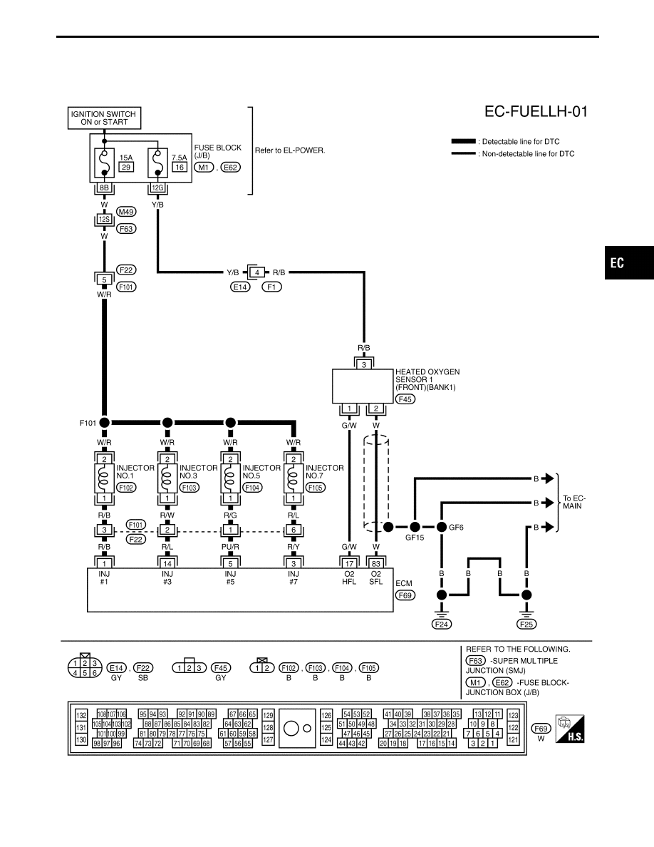
BANK 1
TEC791
GI
MA
EM
LC
FE
AT
PD
FA
RA
BR
ST
RS
BT
HA
EL
IDX
TROUBLE DIAGNOSIS FOR DTC P0172 (B1), P0175 (B2)
Fuel Injection System Function (Rich side)
(P0172: Left bank), (P0175: Right bank)
(Cont’d)
EC-253
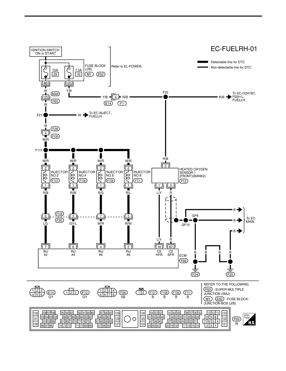
BANK 2
TEC793
TROUBLE DIAGNOSIS FOR DTC P0172 (B1), P0175 (B2)
Fuel Injection System Function (Rich side)
(P0172: Left bank), (P0175: Right bank)
(Cont’d)
EC-254
SEF099P
SEF054TI
SEF056TH
SEF409WA
SEF390UA
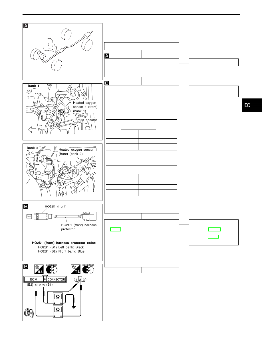
DIAGNOSTIC PROCEDURE
INSPECTION START
CHECK FOR EXHAUST AIR LEAK.
Start engine and run it at idle. Listen for an
exhaust air leak before the three way cata-
lyst.
OK
E
NG
Repair or replace.
CHECK HEATED OXYGEN SENSOR 1
(FRONT).
1. Turn ignition switch “OFF”.
2. Disconnect heated oxygen sensor 1
(front) harness connector and ECM har-
ness connector.
3. Check harness continuity between ECM
and sensor terminals.
Continuity should exist.
4. Check harness continuity between ECM
and sensor or ground.
Continuity should not exist.
If OK, check harness for short to ground
and short to power.
OK
E
NG
Repair harness or connec-
tors.
CHECK FUEL PRESSURE.
1. Release fuel pressure to zero. Refer to
2. Install fuel pressure gauge and check
fuel pressure.
At idle:
Approx. 235 kPa
(2.4 kg/cm
2
, 34 psi)
A few seconds after ignition switch is
turned OFF to ON:
Approx. 294 kPa
(3.0 kg/cm
2
, 43 psi)
OK
E
NG
Check the following.
I
Fuel pump and circuit
Refer to EC-523.
I
Fuel pressure regulator
Refer to EC-37.
If NG, repair or replace.
q
A
(Go to next page.)
DTC
Terminals
Bank
(Harness
protector
color)
ECM
Sensor
P0172
83
2
(B1) (Black)
P0175
82
2
(B2) (Blue)
DTC
Terminals
Bank
(Harness
protector
color)
ECM or
sensor
Ground
P0172
83 or 2
Ground
(B1) (Black)
P0175
82 or 2
Ground
(B2) (Blue)
GI
MA
EM
LC
FE
AT
PD
FA
RA
BR
ST
RS
BT
HA
EL
IDX
TROUBLE DIAGNOSIS FOR DTC P0172 (B1), P0175 (B2)
Fuel Injection System Function (Rich side)
(P0172: Left bank), (P0175: Right bank)
(Cont’d)
H
H
H
H
EC-255
SEF793X
MEC703B
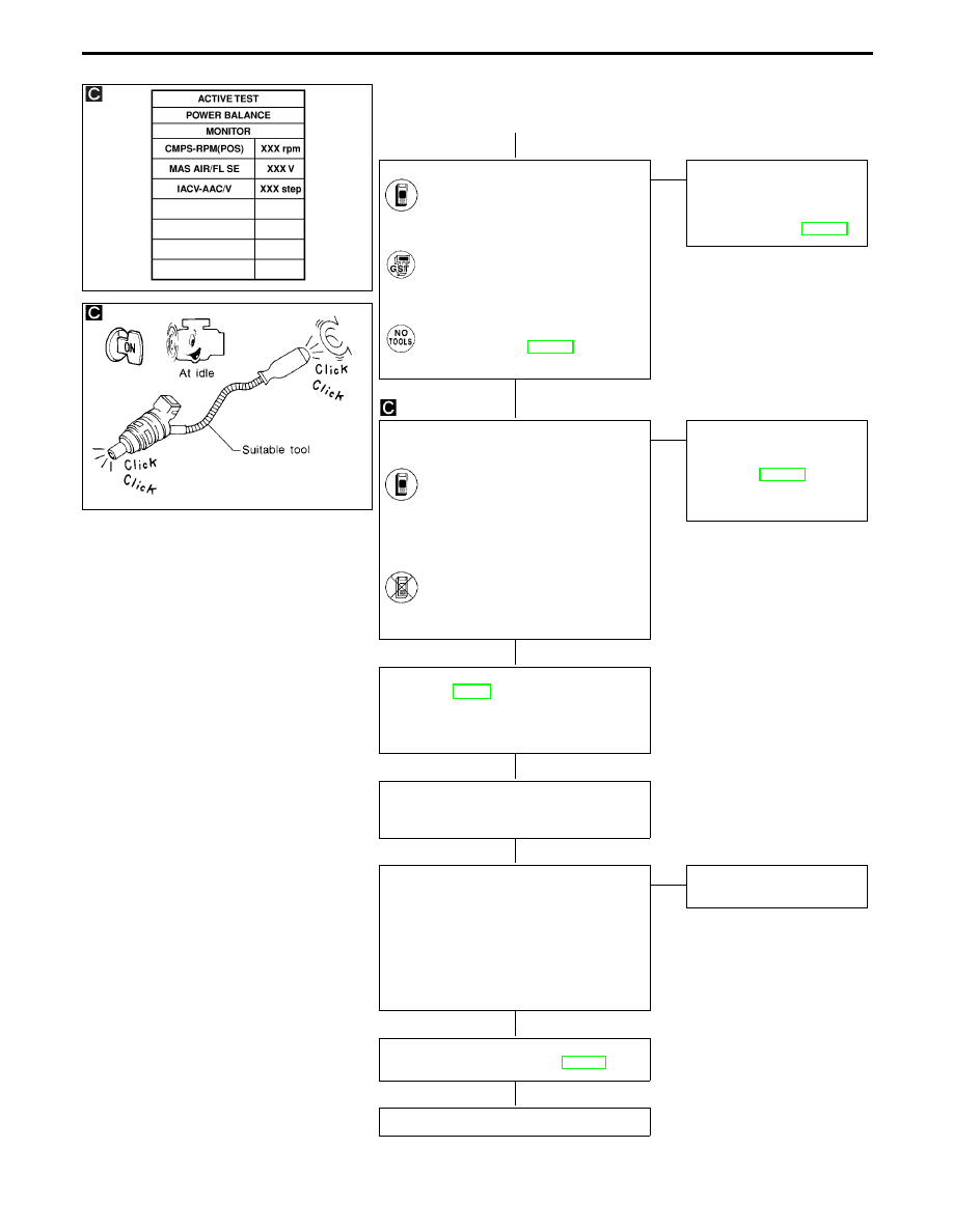
q
A
CHECK MASS AIR FLOW SENSOR.
Check “MASS AIR FLOW” in “DATA
MONITOR” mode with CONSULT-II.
3.0 - 6.0 g
⋅
m/sec: at idling
12.9 - 25.3 g
⋅
m/sec: at 2,500 rpm
-------------------------------------------------------------------------------------------------------------------------------------- OR --------------------------------------------------------------------------------------------------------------------------------------
Check “mass air flow” in MODE 1
with GST.
3.0 - 6.0 g
⋅
m/sec: at idling
12.9 - 25.3 g
⋅
m/sec: at 2,500 rpm
-------------------------------------------------------------------------------------------------------------------------------------- OR --------------------------------------------------------------------------------------------------------------------------------------
Check mass air flow sensor output
voltage, refer to EC-131.
Approximately 2.1V: at 2,500 rpm
OK
E
NG
Check connectors for
rusted terminals or loose
connections in the mass air
flow sensor circuit or engine
grounds. Refer to EC-124.
CHECK FUNCTION OF INJECTORS.
1. Install all parts removed.
2. Start engine.
3. Perform “POWER BALANCE” in
“ACTIVE TEST” mode with CON-
SULT-II.
4. Make sure that each circuit pro-
duces a momentary engine
speed drop.
-------------------------------------------------------------------------------------------------------------------------------------- OR --------------------------------------------------------------------------------------------------------------------------------------
3. Listen to each injector operating
sound.
Clicking noise should be
heard.
OK
E
NG
Perform TROUBLE DIAG-
NOSIS FOR NON-DE-
TECTABLE ITEMS,
“Injectors”, EC-515.
Repair harness or connec-
tors.
1. Remove injector assembly.
2. Refer to EC-38.
Keep fuel hose, all injectors and injector
harness connectors connected to injector
gallery.
Confirm that the engine is cooled down
and there are no fire hazards near the
vehicle.
1. Disconnect all injector harness connec-
tors.
2. Place pans or saucers under each injec-
tor.
3. Disconnect all ignition coil harness con-
nectors.
4. Crank engine for about 3 seconds.
Make sure fuel does not drip from injec-
tor.
Does not drip.
E
Drips Replace the injectors from
which fuel is dripping.
Perform “TROUBLE DIAGNOSIS FOR
INTERMITTENT INCIDENT”, EC-117.
INSPECTION END
TROUBLE DIAGNOSIS FOR DTC P0172 (B1), P0175 (B2)
Fuel Injection System Function (Rich side)
(P0172: Left bank), (P0175: Right bank)
(Cont’d)
H
H
H
H
H
H
H
EC-256
Нет комментариевНе стесняйтесь поделиться с нами вашим ценным мнением.
Текст