Infiniti Q45 (FY33). Manual — part 545
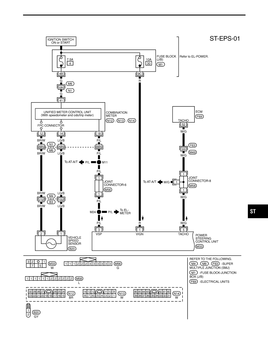
Wiring Diagram
TST002M
GI
MA
EM
LC
EC
FE
AT
PD
FA
RA
BR
RS
BT
HA
EL
IDX
TWIN ORIFICE POWER STEERING SYSTEM
ST-31
TST003M
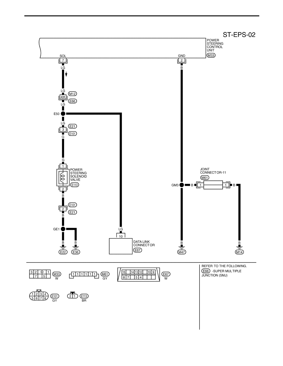
TWIN ORIFICE POWER STEERING SYSTEM
Wiring Diagram (Cont’d)
ST-32
Precautions
BEFORE DIAGNOSING THE POWER STEERING
SYSTEM, ENSURE THAT:
Vehicle stopped
a.
Power steering components (gears, oil pump, pipes, etc.)
are free from leakage, and that oil level is correct.
b.
Tires are inflated to specified pressure and are of speci-
fied size, and that steering wheel is a genuine Nissan part.
c.
Suspension utilizes the original design, and is free of
modifications which increase vehicle weight.
d.
Wheel alignment is adjusted properly.
Vehicle in operation
a.
Understand the trouble symptoms.
b.
Engine is operating properly.
PRELIMINARY KNOWLEDGE HELPFUL IN
CONDUCTING DIAGNOSES
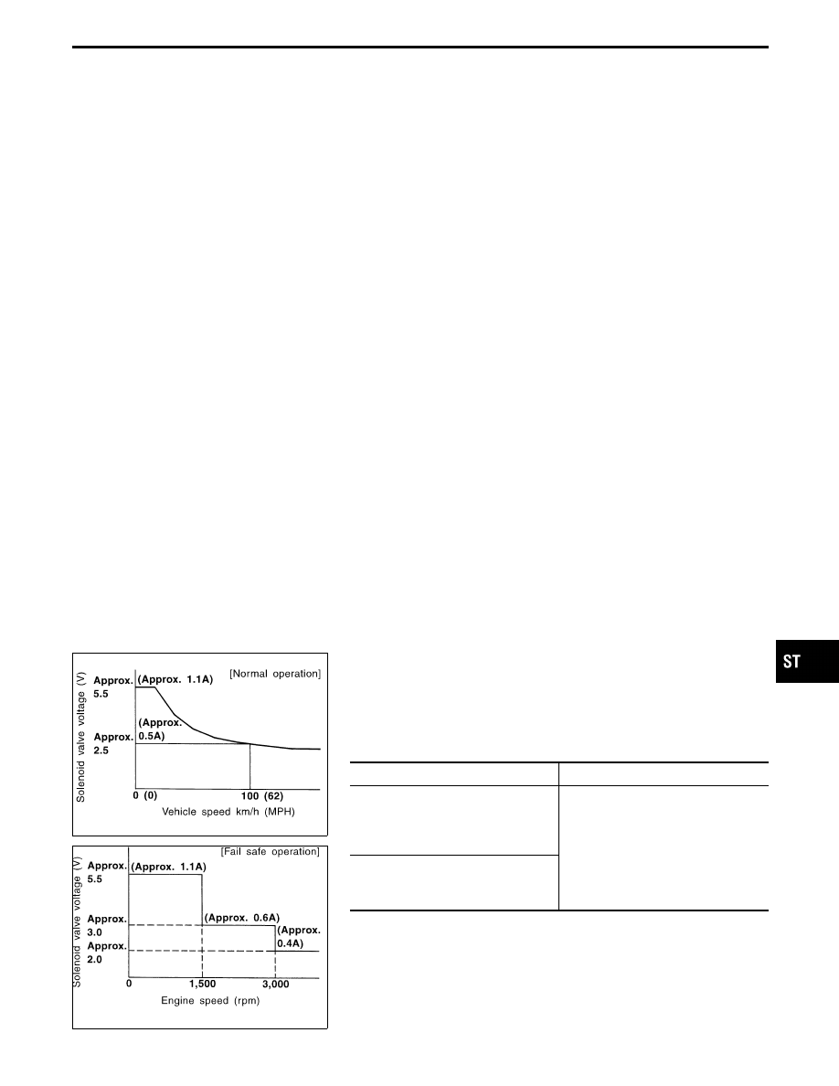
The power steering system is a twin orifice type, which uses a
vehicle-speed sensing, electronic control design. Solenoid valve
sensitivity is controlled in response to vehicle speed to achieve
optimum steering effort.
SST696CA
SST697CB
FAIL-SAFE FUNCTION
The fail-safe function operates to regulate solenoid valve operation
in response to engine speed, thereby maintaining the required
steering force.
Fail-safe input conditions
Fail-safe input conditions
Release conditions
No vehicle speed signal is entered for
at least 10 seconds while driving at an
engine speed of greater than 1,500
rpm.
I
A vehicle speed signal of greater
than 1.4 km/h (0.9 MPH) is entered.
I
Ignition key is turned from “OFF” to
“ON”.
A vehicle speed signal of greater than
30 km/h (19 MPH) abruptly drops
below 2 km/h (1 MPH).
NOTE:
When the engine is revved up to 1,500 rpm or more for at least
10 seconds with the vehicle at standstill, the fail-safe function
operates; however, this is not a matter of concern.
The fail-safe function can be released by driving the vehicle of
a speed of greater than 1.4 km/h (0.9 MPH) or by turning the
ignition key from “OFF” to “ON”.
GI
MA
EM
LC
EC
FE
AT
PD
FA
RA
BR
RS
BT
HA
EL
IDX
TWIN ORIFICE POWER STEERING SYSTEM — Trouble Diagnoses
ST-33
SST872C
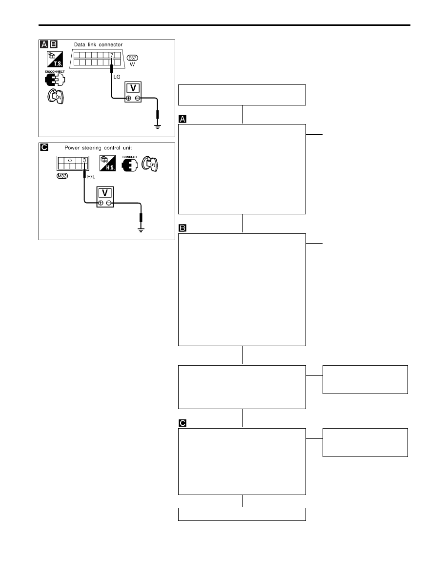
Diagnostic Procedure
SST567CB
SYMPTOM:
I
Heavy steering operation during stationary turns
I
Light steering operation during high-speed driving
Raise rear wheels off ground and start
engine.
CHECK SOLENOID VALVE VOLTAGE.
Measure voltage between solenoid valve
terminal
q
7
of data link connector and
ground while driving vehicle from 0 to 100
km/h (0 to 62 MPH).
Voltage:
0 km/h (0 MPH):
4.4 - 6.6V ... OK
100 km/h (62 MPH):
2.5V ... OK
Constant voltage ... NG
NG
E
OK
q
A
CHECK SOLENOID VALVE VOLTAGE.
Measure voltage between solenoid valve
terminal
q
7
of data link connector and
ground with engine at idle speed, approx.
1,600 rpm, and approx. 3,100 rpm respec-
tively.
Voltage:
Idling:
4.4 - 6.6V ... OK
1,600 rpm (approx.):
3.0V ... OK
3,100 rpm (approx.):
2.0V ... OK
No voltage variations ... NG
OK
E
NG
q
B
CHECK VEHICLE SPEED SENSOR
INPUT SIGNAL.
Check speedometer for proper operation.
YES ... OK
NO ... NG
OK
E
NG
Malfunctioning vehicle
speed sensor or speedom-
eter
Check if vehicle speed signal is present at
power steering control unit.
While driving at very slow speeds, mea-
sure voltage between control unit harness
terminal
q
3
and ground.
0V (Min.) and 5V (Max.) are
alternately repeated ... OK
No voltage is present ... NG
OK
E
NG
Improper connection
between speedometer and
power steering control unit
Malfunctioning power steering control unit
TWIN ORIFICE POWER STEERING SYSTEM — Trouble Diagnoses
H
H
H
H
H
ST-34
Нет комментариевНе стесняйтесь поделиться с нами вашим ценным мнением.
Текст