Infiniti Q45 (FY33). Manual — part 162
SEF833UA
SEF409WA
SEF985Z
SEF395W
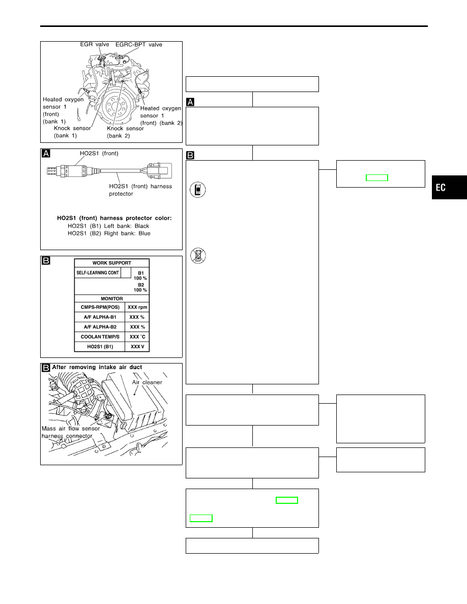
DIAGNOSTIC PROCEDURE
INSPECTION START
Loosen and retighten heated oxygen sen-
sors 1 (front).
Tightening torque:
40 - 50 N
⋅
m
(4.1 - 5.1 kg-m, 30 - 37 ft-lb)
CLEAR THE SELF-LEARNING DATA
1. Start engine and warm it up to normal
operating temperature.
2. Select “SELF-LEARNING
CONT” in “WORK SUPPORT”
mode with CONSULT-II.
3. Clear the self-learning control
coefficient by touching “CLEAR”.
4. Run engine for at least 10 min-
utes at idle speed.
Are the 1st trip DTCs P0171,
P0174 detected? Is it difficult
to start engine?
-------------------------------------------------------------------------------------------------------------------------------------- OR --------------------------------------------------------------------------------------------------------------------------------------
2. Turn ignition switch “OFF”.
3. Disconnect mass air flow sensor
harness connector, and restart
and run engine for at least 3
seconds at idle speed.
4. Stop engine and reconnect
mass air flow sensor harness
connector.
5. Make sure diagnostic trouble
code No. 0102 is displayed in
Diagnostic Test Mode II.
6. Erase the diagnostic test mode
II (Self-diagnostic results)
memory. Make sure diagnostic
trouble code No. 0505 is dis-
played in Diagnostic Test Mode
II.
7. Run engine for at least 10 min-
utes at idle speed.
Are the 1st trip DTCs 0115,
0210 detected? Is it difficult to
start engine?
No
E
Yes
Go to “TROUBLE DIAG-
NOSIS FOR DTC P0171,
P0174”, EC-245.
CHECK COMPONENT
[Heated oxygen sensor 1 heaters (front)].
Refer to “COMPONENT INSPECTION” on
next page.
OK
E
NG
REPLACE HO2S1 (front).
1. Check HO2S1 (front)
harness protector color.
Black: Left bank (B1)
Blue: Right bank (B2)
2. Replace malfunctioning
HO2S1 (front)
CHECK COMPONENT
[Heated oxygen sensors 1 (front)].
Refer to “COMPONENT INSPECTION” on
next page.
OK
E
NG
Replace corresponding
heated oxygen sensor 1
(front).
Perform “TROUBLE DIAGNOSIS FOR
INTERMITTENT INCIDENT”, EC-117.
Refer to “TROUBLE DIAGNOSIS FOR
DTC P0130 (B1), P0150 (B2)” for circuit,
INSPECTION END
GI
MA
EM
LC
FE
AT
PD
FA
RA
BR
ST
RS
BT
HA
EL
IDX
TROUBLE DIAGNOSIS FOR DTC P0131 (B1), P0151 (B2)
Heated Oxygen Sensor 1 (Front) (P0131: Bank
1), (P0151: Bank 2) (Lean shift monitoring)
(Cont’d)
H
H
H
H
H
H
EC-177
AEC158A
COMPONENT INSPECTION
Heated oxygen sensor 1 heater (front)
Check resistance between terminals
q
3
and
q
1
.
Resistance: 2.3 - 4.3
Ω
at 25°C (77°F)
Check continuity between terminals
q
2
and
q
1
,
q
3
and
q
2
.
Continuity should not exist.
If NG, replace the heated oxygen sensor 1 (front).
CAUTION:
I
Discard any heated oxygen sensor which has been
dropped from a height of more than 0.5 m (19.7 in) onto a
hard surface such as a concrete floor; use a new one.
I
Before installing new oxygen sensor, clean exhaust sys-
tem threads using Oxygen Sensor Thread Cleaner tool
J-43897-18 or J-43897-12 and approved anti-seize lubri-
cant.
SEF977Z
Heated oxygen sensor 1 (front)
1) Start engine and warm it up to normal operating tem-
perature.
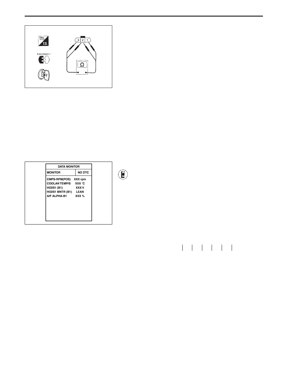
2) Select “MANU TRIG” and “HI SPEED” in “DATA MONI-
TOR” mode with CONSULT-II, and select “HO2S1 (B1)
(B2)” and “HO2S1 MNTR (B1) (B2)”.
3) Hold engine speed at 2,000 rpm under no load during
the following steps.
4) Touch “RECORD” on CONSULT-II screen.
5) Check the following.
I
“HO2S1 MNTR (B1) (B2)” in “DATA MONITOR” mode
changes from “RICH” to “LEAN” to “RICH” 5 times in 10
seconds.
5 times (cycles) are counted as shown below:
cycle
1
2
3
4
5
HO2S1 MNTR (B1) R-L-R-L-R-L-R-L-R-L-R
R = “HO2S1 MNTR (B1) (B2)”, “RICH”
L = “HO2S1 MNTR (B1) (B2)”, “LEAN”
I
“HO2S1 (B1) (B2)” voltage goes above 0.6V at least
once.
I
“HO2S1 (B1) (B2)” voltage goes below 0.30V at least
once.
I
The voltage never exceeds 1.0V.
CAUTION:
I
Discard any heated oxygen sensor which has been
dropped from a height of more than 0.5 m (19.7 in) onto a
hard surface such as a concrete floor; use a new one.
I
Before installing new oxygen sensor, clean exhaust sys-
tem threads using Oxygen Sensor Thread Cleaner tool
J-43897-18 or J-43897-12 and approved anti-seize lubri-
cant.
TROUBLE DIAGNOSIS FOR DTC P0131 (B1), P0151 (B2)
Heated Oxygen Sensor 1 (Front) (P0131: Bank
1), (P0151: Bank 2) (Lean shift monitoring)
(Cont’d)
EC-178
SEF978Z
SEF353WA
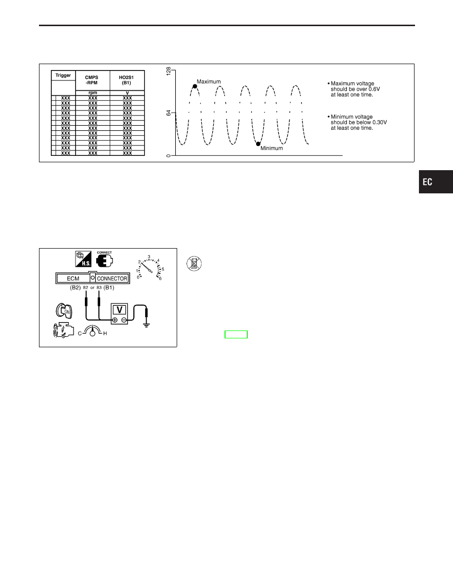
------------------------------------------------------------------------------------------------------------------------------------------------------------------------------------------------------------------------------------------------------ OR ------------------------------------------------------------------------------------------------------------------------------------------------------------------------------------------------------------------------------------------------------
1) Start engine and warm it up to normal operating tem-
perature.
2) Set voltmeter probes between ECM terminal
q
82
(B2),
q
83
(B1) (sensor signal) and ground.
3) Check the following with engine speed held at 2,000
rpm constant under no load.
I
Malfunction indicator lamp goes on more than 5 times
within 10 seconds in Diagnostic Test Mode II [HEATED
OXYGEN SENSOR 1 MONITOR (FRONT)]. See
EC-68.
I
The maximum voltage is over 0.6V at least one time.
I
The minimum voltage is below 0.30V at least one time.
I
The voltage never exceeds 1.0V.
CAUTION:
I
Discard any heated oxygen sensor which has been
dropped from a height of more than 0.5 m (19.7 in) onto a
hard surface such as a concrete floor; use a new one.
I
Before installing new oxygen sensor, clean exhaust sys-
tem threads using Oxygen Sensor Thread Cleaner tool
J-43897-18 or J-43897-12 and approved anti-seize lubri-
cant.
GI
MA
EM
LC
FE
AT
PD
FA
RA
BR
ST
RS
BT
HA
EL
IDX
TROUBLE DIAGNOSIS FOR DTC P0131 (B1), P0151 (B2)
Heated Oxygen Sensor 1 (Front) (P0131: Bank
1), (P0151: Bank 2) (Lean shift monitoring)
(Cont’d)
EC-179
SEF463R
Heated Oxygen Sensor 1 (Front) (P0132: Bank
1), (P0152: Bank 2) (Rich Shift Monitoring)
SEF288D
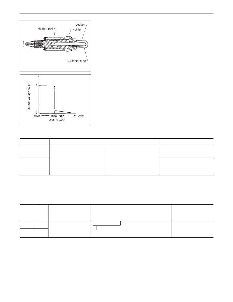
COMPONENT DESCRIPTION
The heated oxygen sensor 1 (front) is placed into the exhaust
manifold. It detects the amount of oxygen in the exhaust gas com-
pared to the outside air. The heated oxygen sensor 1 (front) has a
closed-end tube made of ceramic zirconia. The zirconia generates
voltage from approximately 1V in richer conditions to 0V in leaner
conditions. The heated oxygen sensor 1 (front) signal is sent to the
ECM. The ECM adjusts the injection pulse duration to achieve the
ideal air-fuel ratio. The ideal air-fuel ratio occurs near the radical
change from 1V to 0V.
CONSULT-II REFERENCE VALUE IN DATA MONITOR MODE
Specification data are reference values.
MONITOR ITEM
CONDITION
SPECIFICATION
HO2S1 (B1)
HO2S1 (B2)
I
Engine: After warming up
Maintaining engine speed at 2,000 rpm
0 - 0.3V
)
0.6 - 1.0V
HO2S1 MNTR (B1)
HO2S1 MNTR (B2)
LEAN
)
RICH
Changes more than 5 times
during 10 seconds.
ECM TERMINALS AND REFERENCE VALUE
Specification data are reference values, and are measured between each terminal and ground.
CAUTION:
Do not use ECM ground terminals when measuring voltage. Doing so may result in damage to the
ECM’s transistor. Use a ground other than ECM terminals such as the body ground.
TER-
MINAL
NO.
WIRE
COLOR
ITEM
CONDITION
DATA
(DC voltage)
82 (B2)
R
Heated oxygen sensors 1
(front)
Engine is running.
After warming up to normal operating tempera-
ture and engine speed is 2,000 rpm.
0 - Approximately 1.0V
(periodically change)
83 (B1)
W
TROUBLE DIAGNOSIS FOR DTC P0132 (B1), P0152 (B2)
EC-180
Нет комментариевНе стесняйтесь поделиться с нами вашим ценным мнением.
Текст