Infiniti Q45 (FY33). Manual — part 163
SEF299U
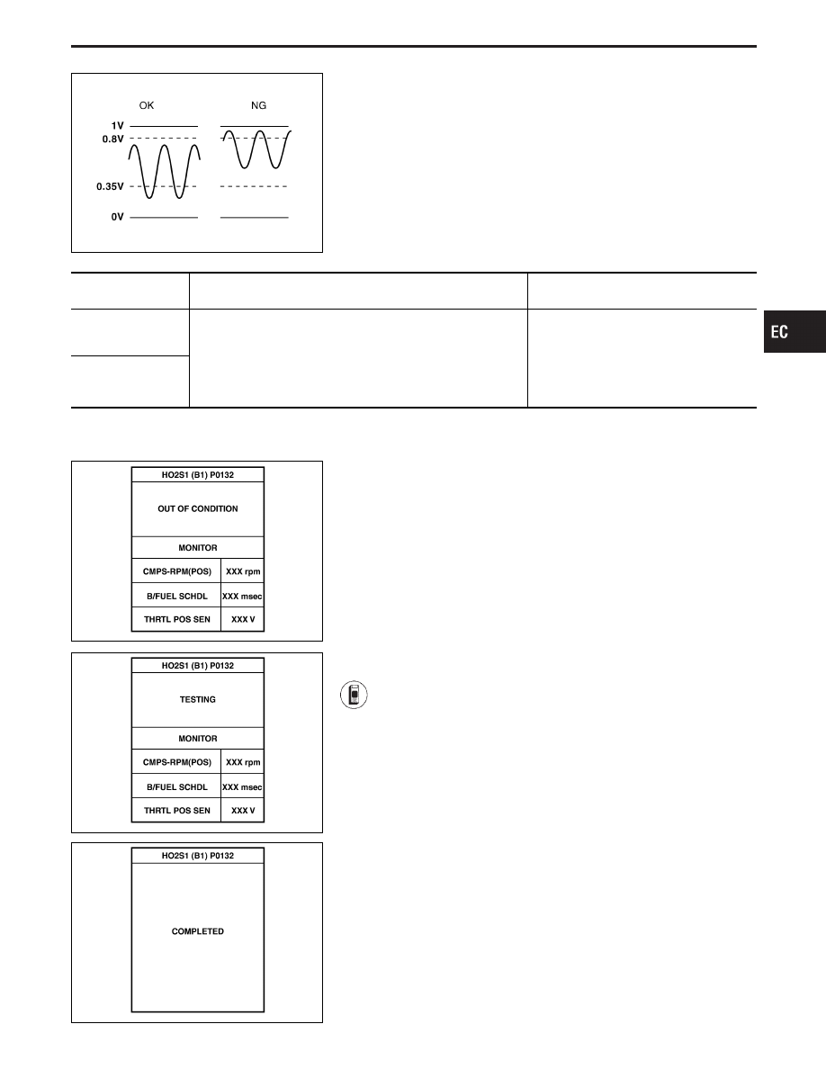
ON BOARD DIAGNOSIS LOGIC
To judge the malfunction, the output from the heated oxygen sen-
sor 1 (front) is monitored to determine whether the “rich” output is
sufficiently high. The “lean” output is sufficiently low. When both the
outputs are shifting to the rich side, the malfunction will be
detected.
Diagnostic Trouble
Code No.
Malfunction is detected when ...
Check Items
(Possible Cause)
P0132
0410
(Bank 1)
I
The maximum and minimum voltages from the sensor are not
around the specified voltages.
I
Heated oxygen sensor 1 (front)
I
Heated oxygen sensor 1 heater (front)
I
Fuel pressure
I
Injectors
P0152
0414
(Bank 2)
SEF986Z
SEF987Z
SEF655Y
DIAGNOSTIC TROUBLE CODE CONFIRMATION
PROCEDURE
CAUTION:
Always drive vehicle at a safe speed.
NOTE:
If “DIAGNOSTIC TROUBLE CODE CONFIRMATION PROCE-
DURE” has been previously conducted, always turn ignition
switch “OFF” and wait at least 5 seconds before conducting
the next test.
TESTING CONDITION:
I
Always perform at a temperature above −10°C (14°F).
I
Before performing following procedure, confirm that bat-
tery voltage is more than 11V at idle.
1) Start engine and warm it up to normal operating tem-
perature.
2) Stop engine and wait at least 5 seconds.
3) Turn ignition switch “ON” and select “HO2S1 (B1)
P0132, (B2) P0152” of “HO2S1” in “DTC WORK SUP-
PORT” mode with CONSULT-II.
4) Touch “START”.
5) Start engine (TCS switch “OFF”) and let it idle for at
least 3 minutes.
NOTE:
Never raise engine speed above 3,200 rpm after this
step. If the engine speed limit is exceeded, return to
step 5).
6) When the following conditions are met, “TESTING” will
be displayed on the CONSULT-II screen. Maintain the
conditions continuously until “TESTING” changes to
“COMPLETED”. (It will take approximately 50 seconds.)
CMPS-RPM (POS): 1,200 - 2,200 rpm
Vehicle speed: 0 - 100 km/h (0 - 62 MPH)
B/FUEL SCHDL: 1.4 - 5.0 ms
Selector lever: Suitable position
GI
MA
EM
LC
FE
AT
PD
FA
RA
BR
ST
RS
BT
HA
EL
IDX
TROUBLE DIAGNOSIS FOR DTC P0132 (B1), P0152 (B2)
Heated Oxygen Sensor 1 (Front) (P0132: Bank
1), (P0152: Bank 2) (Rich Shift Monitoring)
(Cont’d)
EC-181
If “TESTING” is not displayed after 5 minutes, retry
from step 2).
7) Make sure that “OK” is displayed after touching “SELF-
DIAG RESULTS”. If “NG” is displayed, refer to “DIAG-
NOSTIC PROCEDURE”, EC-183.
SEF353WA
------------------------------------------------------------------------------------------------------------------------------------------------------------------------------------------------------------------------------------------------------ OR ------------------------------------------------------------------------------------------------------------------------------------------------------------------------------------------------------------------------------------------------------
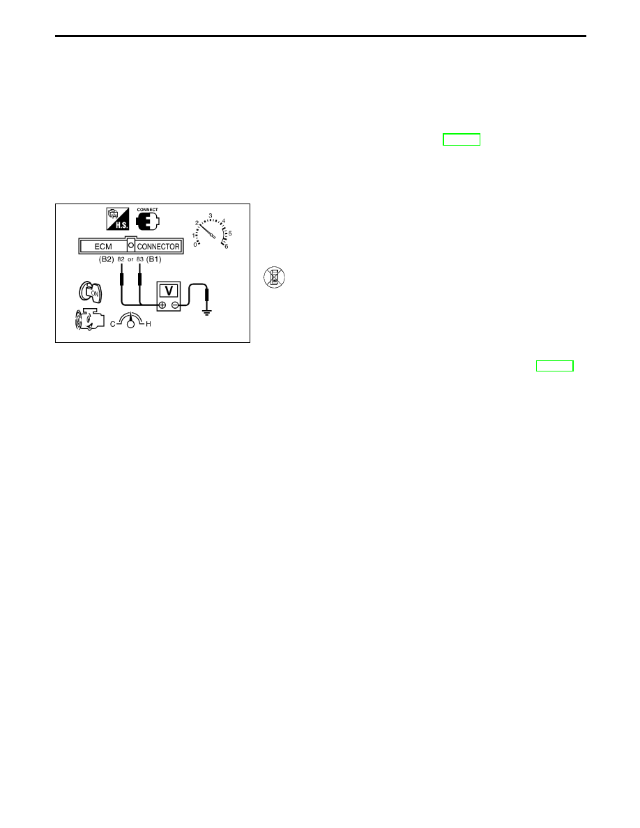
OVERALL FUNCTION CHECK
Use this procedure to check the overall function of the heated oxy-
gen sensor 1 (front) circuit. During this check, a 1st trip DTC might
not be confirmed.
1) Start engine and warm it up to normal operating tem-
perature.
2) Set voltmeter probes between ECM terminal
q
82
(B2),
q
83
(B1) (sensor signal) and ground.
3) Check the following with engine speed held at 2,000
rpm constant under no load.
I
The maximum voltage is over 0.8V at least one time.
I
The minimum voltage is below 0.35V at least one time.
4) If NG, go to “DIAGNOSTIC PROCEDURE”, EC-183.
TROUBLE DIAGNOSIS FOR DTC P0132 (B1), P0152 (B2)
Heated Oxygen Sensor 1 (Front) (P0132: Bank
1), (P0152: Bank 2) (Rich Shift Monitoring)
(Cont’d)
EC-182
SEF833UA
SEF985Z
SEF395W
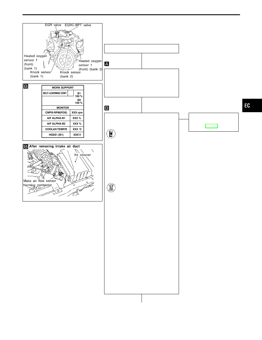
DIAGNOSTIC PROCEDURE
INSPECTION START
Loosen and retighten heated oxygen sen-
sor 1 (front).
Tightening torque:
40 - 50 N
⋅
m (4.1 - 5.1 kg-m, 30 - 37
ft-lb)
CLEAR THE SELF-LEARNING DATA
1. Start engine and warm it up to normal
operating temperature.
2. Select “SELF-LEARNING
CONT” in “WORK SUPPORT”
mode with CONSULT-II.
3. Clear the self-learning control
coefficient by touching “CLEAR”.
4. Run engine for at least 10 min-
utes at idle speed.
Are the 1st trip DTCs P0172,
P0175 detected? Is it difficult
to start engine?
-------------------------------------------------------------------------------------------------------------------------------------- OR --------------------------------------------------------------------------------------------------------------------------------------
2. Turn ignition switch “OFF”.
3. Disconnect mass air flow sensor
harness connector, and restart
and run engine for at least 3
seconds at idle speed.
4. Stop engine and reconnect
mass air flow sensor harness
connector.
5. Make sure diagnostic trouble
code No. 0102 is displayed in
Diagnostic Test Mode II.
6. Erase the diagnostic test mode
II (Self-diagnostic results)
memory. Make sure diagnostic
trouble code No. 0505 is dis-
played in Diagnostic Test Mode
II.
7. Run engine for at least 10 min-
utes at idle speed.
Are the 1st trip DTCs 0114,
0209 detected? Is it difficult to
start engine?
No
E
Yes
Go to “TROUBLE DIAG-
NOSIS FOR DTC P0172,
P0175”, EC-251.
q
A
(Go to next page.)
GI
MA
EM
LC
FE
AT
PD
FA
RA
BR
ST
RS
BT
HA
EL
IDX
TROUBLE DIAGNOSIS FOR DTC P0132 (B1), P0152 (B2)
Heated Oxygen Sensor 1 (Front) (P0132: Bank
1), (P0152: Bank 2) (Rich Shift Monitoring)
(Cont’d)
H
H
H
EC-183
q
A
CHECK COMPONENT
[Heated oxygen sensor 1 heater (front)].
Refer to “COMPONENT INSPECTION” on
next page.
OK
E
NG
REPLACE HO2S1 (front).
1. Check HO2S1 (front)
harness protector color.
Black: Left bank (B1)
Blue: Right bank (B2)
2. Replace malfunctioning
HO2S1 (front).
CHECK COMPONENT
[Heated oxygen sensor 1 (front)].
1. Turn ignition switch “OFF”.
2. Disconnect sensor harness connector
and check for water.
Water should not exist.
If OK, go to step 3.
3. Check heated oxygen sensor 1 (front)
(B1), (B2).
Refer to “COMPONENT INSPECTION” on
next page.
OK
E
NG
Repair or replace harness
and/or connectors or
replace corresponding
heated oxygen sensor 1
(front).
Perform “TROUBLE DIAGNOSIS FOR
INTERMITTENT INCIDENT”, EC-117.
Refer to “TROUBLE DIAGNOSIS FOR
DTC P0130 (B1), P0150 (B2)” for circuit,
EC-166.
OK
INSPECTION END
AEC158A
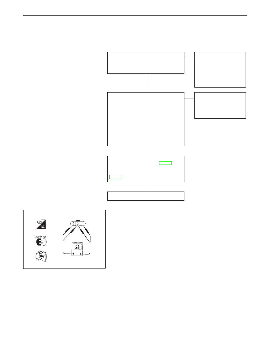
COMPONENT INSPECTION
Heated oxygen sensor 1 heater (front)
Check resistance between terminals
q
3
and
q
1
.
Resistance: 2.3 - 4.3
Ω
at 25°C (77°F)
Check continuity between terminals
q
2
and
q
1
,
q
3
and
q
2
.
Continuity should not exist.
If NG, replace the heated oxygen sensors 1 (front).
CAUTION:
I
Discard any heated oxygen sensor which has been
dropped from a height of more than 0.5 m (19.7 in) onto a
hard surface such as a concrete floor; use a new one.
I
Before installing new oxygen sensor, clean exhaust sys-
tem threads using Oxygen Sensor Thread Cleaner tool
J-43897-18 or J-43897-12 and approved anti-seize lubri-
cant.
TROUBLE DIAGNOSIS FOR DTC P0132 (B1), P0152 (B2)
Heated Oxygen Sensor 1 (Front) (P0132: Bank
1), (P0152: Bank 2) (Rich Shift Monitoring)
(Cont’d)
H
H
H
H
EC-184
Нет комментариевНе стесняйтесь поделиться с нами вашим ценным мнением.
Текст