Infiniti Q45 (FY33). Manual — part 138

Monitored item
[Unit]
ECM
input
signals
Main
signals
Description
Remarks
FPCM [LOW/HI]
I
The control condition of the fuel pump
control module (FPCM) (determined by
ECM according to the input signal) is
indicated.
LOW ... Low amount of fuel flow
HI ... High amount of fuel flow
MAP/BARO SW/V
[MAP/BARO]
I
The control condition of the MAP/BARO
switch solenoid valve (determined by
ECM according to the input signal) is
indicated.
MAP ... Intake manifold absolute pressure
BARO ... Barometric pressure
ABSOL PRES/SE [V]
q
I
The signal voltage of the absolute pres-
sure sensor is displayed.
VOLTAGE
[V]
I
Voltage measured by the voltage probe.
Frequency
[msec] or [Hz] or [%]
I
Pulse width, frequency or duty cycle
measured by the pulse probe.
I
Only “#” is displayed if item is unable to
be measured.
I
Figures with “#”s are temporary ones.
They are the same figures as an actual
piece of data which was just previously
measured.
GI
MA
EM
LC
FE
AT
PD
FA
RA
BR
ST
RS
BT
HA
EL
IDX
ON BOARD DIAGNOSTIC SYSTEM DESCRIPTION
CONSULT-II (Cont’d)
EC-81

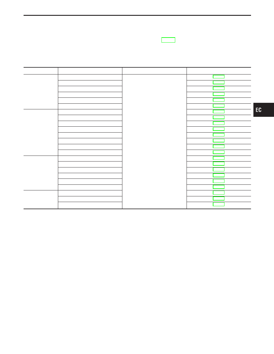
ACTIVE TEST MODE
TEST ITEM
CONDITION
JUDGEMENT
CHECK ITEM (REMEDY)
FUEL INJECTION
I
Engine: Return to the original trouble
condition
I
Change the amount of fuel injection
using CONSULT-II.
If trouble symptom disappears, see
CHECK ITEM.
I
Harness and connector
I
Fuel injectors
I
Heated oxygen sensor 1 (front)
IGNITION TIMING
I
Engine: Return to the original trouble
condition
I
Timing light: Set
I
Retard the ignition timing using
CONSULT-II.
If trouble symptom disappears, see
CHECK ITEM.
I
Adjust ignition timing (by moving
camshaft position sensor)
IACV-AAC/V
OPENING
I
Engine: After warming up, idle the
engine.
I
Change the IACV-AAC valve opening
step using CONSULT-II.
Engine speed changes according to the
opening percent.
I
Harness and connector
I
IACV-AAC valve
POWER BALANCE
I
Engine: After warming up, idle the
engine.
I
A/C switch “OFF”
I
Shift lever “N”
I
Cut off each injector signal one at a
time using CONSULT-II.
Engine runs rough or dies.
I
Harness and connector
I
Compression
I
Injectors
I
Ignition coil with power transistor
I
Spark plugs
COOLING FAN
I
Ignition switch: ON
I
Turn the cooling fan “ON” and “OFF”
using CONSULT-II.
Cooling fan moves and stops.
I
Harness and connector
I
Cooling fan motor
ENG COOLANT
TEMP
I
Engine: Return to the original trouble
condition
I
Change the engine coolant
temperature using CONSULT-II.
If trouble symptom disappears, see
CHECK ITEM.
I
Harness and connector
I
Engine coolant temperature sensor
I
Fuel injectors
FUEL PUMP RELAY
I
Ignition switch: ON (Engine stopped)
I
Turn the fuel pump relay “ON” and
“OFF” using CONSULT-II and listen to
operating sound.
Fuel pump relay makes the operating
sound.
I
Harness and connector
I
Fuel pump relay
EGRC SOLENOID
VALVE
I
Ignition switch: ON
I
Turn solenoid valve “ON” and “OFF”
with CONSULT-II and listen to
operating sound.
Solenoid valve makes an operating
sound.
I
Harness and connector
I
EGRC-solenoid valve
VALVE TIMING SOL
I
Ignition switch: ON
I
Turn solenoid valve “ON” and “OFF”
with CONSULT-II and listen to
operating sound.
Solenoid valve makes an operating
sound.
I
Harness and connector
I
Intake valve timing control solenoid
valve
PURG VOL CONT/V
I
Engine: After warming up, run engine
at 1,500 rpm.
I
Change the EVAP canister purge
volume control valve opening step
using CONSULT-II.
Engine speed changes according to the
opening step.
I
Harness and connector
I
EVAP canister purge volume control
valve
FUEL/T TEMP SEN
I
Change the fuel tank temperature using CONSULT-II.
VENT CONTROL/V
I
Ignition switch: ON (Engine stopped)
I
Turn the VENT CONT/V “ON and
OFF” with CONSULT-II and listen for
operating sound.
Solenoid valve makes an operating
sound.
I
Harness or connector
I
EVAP canister vent control valve
PURG CONT S/V
I
Engine: Run engine at 2,000 rpm.
I
Turn the EVAP canister purge control
solenoid valve “ON” and “OFF” using
CONSULT-II and listen for operating
sound.
EVAP canister purge control solenoid
valve makes an operating sound.
Check vacuum signal for EVAP canister
purge control valve.
VC ON ... Vacuum exists.
VC OFF ... Vacuum does not exist.
I
Harness and connector
I
EVAP canister purge control solenoid
valve
I
Vacuum hose
MAP/BARO SW/V
I
Ignition switch: ON
(Engine stopped)
I
Turn the MAP/BARO switch solenoid
valve between “MAP” and “BARO”
using CONSULT-II and listen for
operating sound.
MAP/BARO switch solenoid valve makes
an operating sound.
I
Harness and connector
I
MAP/BARO switch solenoid valve
FPCM
I
Ignition switch: ON
I
Select “LOW” and “HI” with
CONSULT-II and check that “FPCM
D/R VOLT” of CONSULT-II changes.
“FPCM D/R VOLT” of CONSULT-II
changes as follows;
LOW ... Approx. 4.7V
HI ... Approx. 0.4V
I
Harness and connector
I
FPCM
VC/V BYPASS/V
I
Ignition switch: ON (Engine stopped)
I
Turn the VC/V BYPASS/V “ON and
OFF” with CONSULT-II and listen for
operating sound.
Solenoid valve makes an operating
sound.
I
Harness or connector
I
Vacuum cut bypass valve
ON BOARD DIAGNOSTIC SYSTEM DESCRIPTION
CONSULT-II (Cont’d)
EC-82
DTC & SRT CONFIRMATION MODE
SRT STATUS mode
For details, refer to “SYSTEM READINESS TEST (SRT) CODE”, EC-51.
SRT WORK SUPPORT mode
This mode enables a technician to drive a vehicle to set the SRT while monitoring the SRT status.
DTC WORK SUPPORT mode
Test mode
Test item
Condition
Reference page
EVAPORATIVE
SYSTEM
EVAP SML LEAK P0440
Refer to corresponding trouble diagnosis
for DTC.
EVAP SML LEAK P1440
PURG VOL CN/V P1444
PURGE FLOW P1447
VC CUT/V BP/V P1491
PURG CN/V & S/V P1493
HO2S1
HO2S1 (B1) P0130
HO2S1 (B1) P0131
HO2S1 (B1) P0132
HO2S1 (B1) P0133
HO2S1 (B2) P0150
HO2S1 (B2) P0151
HO2S1 (B2) P0152
HO2S1 (B2) P0153
HO2S2
HO2S2 (B1) P0137
HO2S2 (B1) P0138
HO2S2 (B1) P0139
HO2S2 (B2) P0157
HO2S2 (B2) P0158
HO2S2 (B2) P0159
EGR SYSTEM
EGR SYSTEM P0400
EGRC-BPT/VLV P0402
EGR SYSTEM P1402
GI
MA
EM
LC
FE
AT
PD
FA
RA
BR
ST
RS
BT
HA
EL
IDX
ON BOARD DIAGNOSTIC SYSTEM DESCRIPTION
CONSULT-II (Cont’d)
EC-83
DATA MONITOR
Recording Data...11%
CMPS-RPM (POS)
MAS AIR/FL SE
COOLAN TEMP/S
HO2S1 (B1)
VHCL SPEED SE
XXX rpm
NO DTC
XXX V
XXX ˚C
XXX V
XXX km/h
SEF974Z
SEF707X
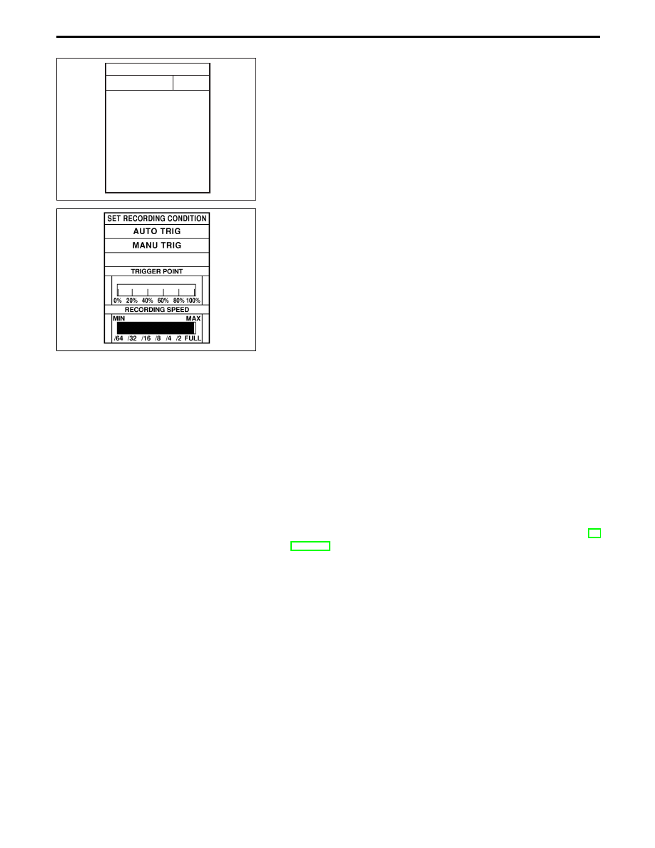
REAL TIME DIAGNOSIS IN DATA MONITOR MODE
(Recording Vehicle Data)
CONSULT-II has two kinds of triggers and they can be selected by
touching “SETTING” in “DATA MONITOR” mode.
1)
“AUTO TRIG” (Automatic trigger):
I
The malfunction will be identified on the CONSULT-II screen
inreal time.
In other words, DTC/1st trip DTC and malfunction item will be
displayed if the malfunction is detected by ECM.
At the moment a malfunction is detected by ECM, “MONITOR”
in “DATA MONITOR” screen is changed to “Recording Data
...xx%” as shown at left, and the data after the malfunction
detection is recorded. Then when the percentage reached
100%, “REAL-TIME DIAG” screen is displayed. If “STOP” is
touched on the screen during “ Recording Data ... xx%”,
“REAL-TIME DIAG” screen is also displayed.
The recording time after the malfunction detection and the
recording speed can be changed by “TRIGGER POINT” and
“Recording Speed”. Refer to CONSULT-II OPERATION
MANUAL.
2)
“MANU TRIG” (Manual trigger):
I
DTC/1st trip DTC and malfunction item will not be displayed
automatically on CONSULT-II screen even though a malfunc-
tion is detected by ECM.
DATA MONITOR can be performed continuously even though
a malfunction is detected.
Use these triggers as follows:
1)
“AUTO TRIG”
I
While trying to detect the DTC/1st trip DTC by performing the
“DTC Confirmation Procedure”, be sure to select to “DATA
MONITOR (AUTO TRIG)” mode. You can confirm the malfunc-
tion at the moment it is detected.
I
While narrowing down the possible causes, CONSULT-II
should be set in “DATA MONITOR (AUTO TRIG)” mode, espe-
cially in case the incident is intermittent.
When you are inspecting the circuit by gently shaking (or twist-
ing) the suspicious connectors, components and harness in
the “DTC Confirmation Procedure”, the moment a malfunction
is found the DTC/1st trip DTC will be displayed. (Refer to GI
Section, “Incident Simulation Tests”.)
2)
“MANU TRIG”
I
If the malfunction is displayed as soon as “DATA MONITOR”
is selected, reset CONSULT-II to “MANU TRIG”. By selecting
“MANU TRIG” you can monitor and store the data. The data
can be utilized for further diagnosis, such as a comparison with
the value for the normal operating condition.
ON BOARD DIAGNOSTIC SYSTEM DESCRIPTION
CONSULT-II (Cont’d)
EC-84
Нет комментариевНе стесняйтесь поделиться с нами вашим ценным мнением.
Текст