Infiniti Q45 (FY33). Manual — part 202
SEF568P
SEF638U
------------------------------------------------------------------------------------------------------------------------------------------------------------------------------------------------------------------------------------------------------ OR ------------------------------------------------------------------------------------------------------------------------------------------------------------------------------------------------------------------------------------------------------
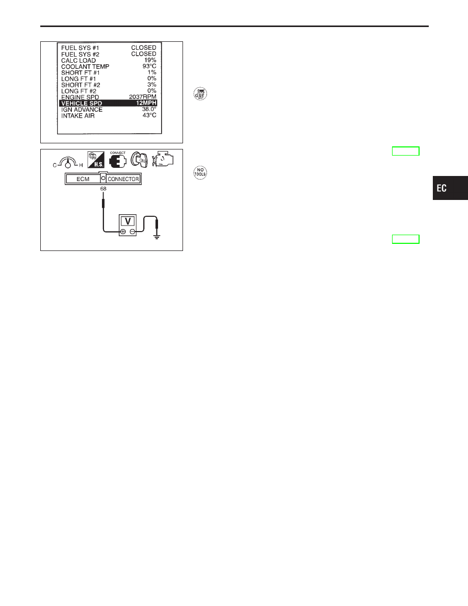
OVERALL FUNCTION CHECK
Use this procedure to check the overall function of the vehicle
speed sensor circuit. During this check, a DTC might not be con-
firmed.
1) Lift up drive wheels.
2) Start engine (TCS switch “OFF”).
3) Read vehicle speed sensor signal in “MODE 1” with
GST.
The vehicle speed sensor on GST should be able to
exceed 10 km/h (6 MPH) when rotating wheels with
suitable gear position.
4) If NG, go to “DIAGNOSTIC PROCEDURE”, EC-339.
------------------------------------------------------------------------------------------------------------------------------------------------------------------------------------------------------------------------------------------------------ OR ------------------------------------------------------------------------------------------------------------------------------------------------------------------------------------------------------------------------------------------------------
1) Lift up drive wheels.
2) Start engine (TCS switch “OFF”).
3) Read the voltage signal between ECM terminal
q
68
(Vehicle speed sensor signal) and ground with oscillo-
scope.
4) Verify that the oscilloscope screen shows the signal
wave as shown at “ECM TERMINALS AND REFER-
ENCE VALUE” on previous page.
5) If NG, go to “DIAGNOSTIC PROCEDURE”, EC-339.
GI
MA
EM
LC
FE
AT
PD
FA
RA
BR
ST
RS
BT
HA
EL
IDX
TROUBLE DIAGNOSIS FOR DTC P0500
Vehicle Speed Sensor (VSS) (Cont’d)
EC-337
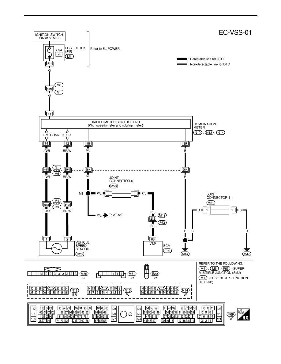
TEC060M
TROUBLE DIAGNOSIS FOR DTC P0500
Vehicle Speed Sensor (VSS) (Cont’d)
EC-338
SEF748W
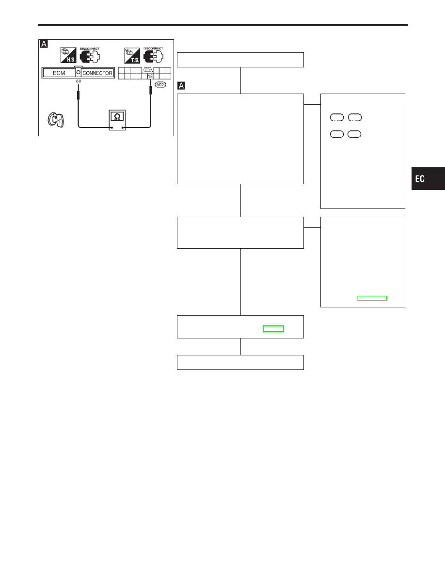
DIAGNOSTIC PROCEDURE
INSPECTION START
CHECK INPUT SIGNAL CIRCUIT.
1. Turn ignition switch “OFF”.
2. Disconnect ECM harness connector
and combination meter harness con-
nector.
3. Check harness continuity between ECM
terminal
q
68
and terminal
q
18
.
Continuity should exist.
If OK, check harness for short to
ground and short to power.
OK
E
NG
Check the following.
I
Harness connectors
F63
,
M49
I
Harness connectors
M6
,
N1
I
Joint connector-6
I
Harness for open or
short between ECM and
combination meter
If NG, repair open circuit or
short to ground or short to
power in harness or con-
nectors.
CHECK SPEEDOMETER FUNCTION.
Make sure that speedometer functions
properly.
OK
E
NG
Check the following.
I
Harness for open or
short between combina-
tion meter and vehicle
speed sensor
If NG, repair harness or
connectors.
I
Vehicle speed sensor
and its circuit
(Refer to EL section.)
Perform “TROUBLE DIAGNOSIS FOR
INTERMITTENT INCIDENT”, EC-117.
INSPECTION END
GI
MA
EM
LC
FE
AT
PD
FA
RA
BR
ST
RS
BT
HA
EL
IDX
TROUBLE DIAGNOSIS FOR DTC P0500
Vehicle Speed Sensor (VSS) (Cont’d)
H
H
H
H
EC-339
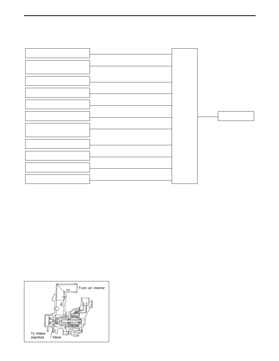
Idle Air Control Valve (IACV) — Auxiliary Air
Control (AAC) Valve
SYSTEM DESCRIPTION
Camshaft position sensor
E
Engine speed
ECM
E
IACV-AAC valve
Engine coolant temperature sen-
sor
E
Engine coolant temperature
Ignition switch
E
Start signal
Throttle position sensor
E
Throttle position
PNP switch
E
Park/Neutral position
Air conditioner switch
E
Air conditioner operation
Power steering oil pressure
switch
E
Power steering load signal
Battery
E
Battery voltage
Vehicle speed sensor
E
Vehicle speed
Cooling fan
E
Cooling fan operation
Electrical load
E
Electrical load signal
This system automatically controls engine idle speed to a specified level. Idle speed is controlled through fine
adjustment of the amount of air which by-passes the throttle valve via IACV-AAC valve. The IACV-AAC valve
changes the opening of the air by-pass passage to control the amount of auxiliary air. This valve is actuated
by a step motor built into the valve, which moves the valve in the axial direction in steps corresponding to the
ECM output signals. One step of IACV-AAC valve movement causes the respective opening of the air by-pass
passage. (i.e. when the step advances, the opening is enlarged.) The opening of the valve is varied to allow
for optimum control of the engine idling speed. The camshaft position sensor detects the actual engine speed
and sends a signal to the ECM. The ECM then controls the step position of the IACV-AAC valve so that engine
speed coincides with the target value memorized in ECM. The target engine speed is the lowest speed at which
the engine can operate steadily. The optimum value stored in the ECM is determined by taking into consid-
eration various engine conditions, such as during warm up, deceleration, and engine load (air conditioner,
power steering and cooling fan operation).
SEF765P
COMPONENT DESCRIPTION
The IACV-AAC valve is operated by a step motor for centralized
control of auxiliary air supply. This motor has four winding phases
and is actuated by the output signals of ECM which turns ON and
OFF two windings each in sequence. Each time the IACV-AAC
valve opens or closes to change the auxiliary air quantity, the ECM
sends a pulse signal to the step motor. When no change in the
auxiliary air quantity is needed, the ECM does not issue the pulse
signal. A certain voltage signal is issued so that the valve remains
at that particular opening.
TROUBLE DIAGNOSIS FOR DTC P0505
EC-340
Нет комментариевНе стесняйтесь поделиться с нами вашим ценным мнением.
Текст