Infiniti Q45 (FY33). Manual — part 200
SEF434Q
SEF419U
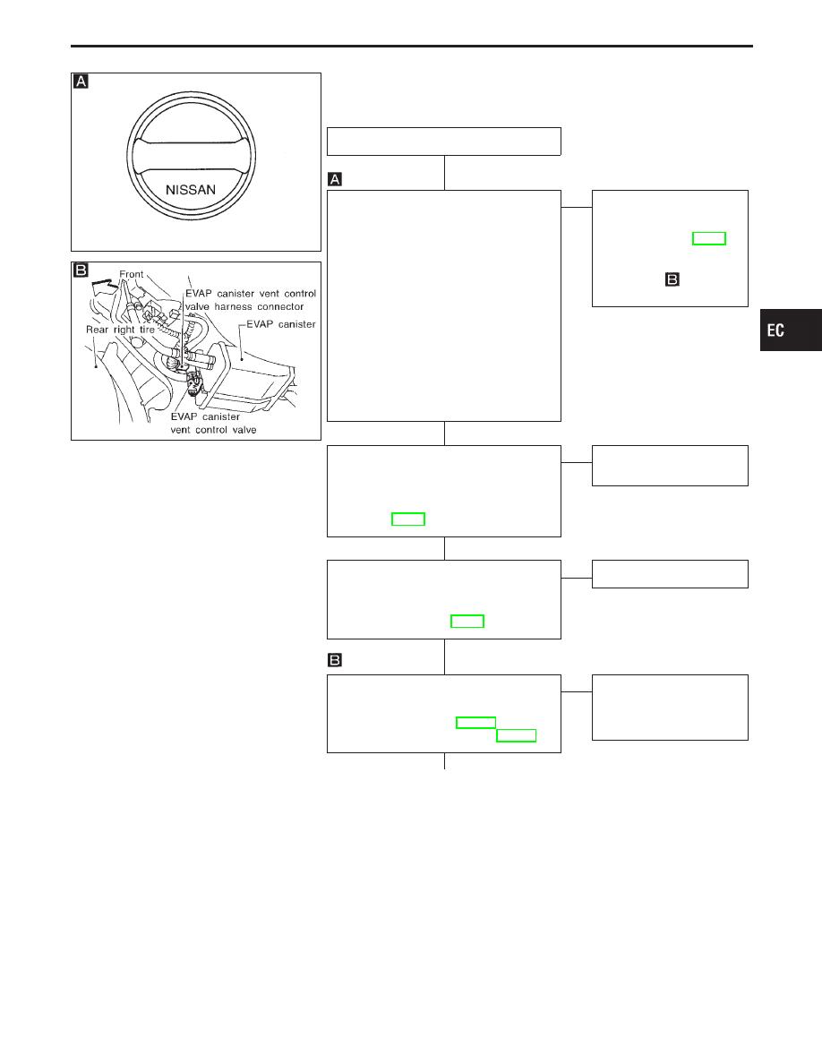
DIAGNOSTIC PROCEDURE
INSPECTION START
CHECK FUEL FILLER CAP.
1. Turn ignition switch “OFF”.
2. Check for genuine NISSAN fuel filler
cap design.
If NG, replace with genuine NISSAN
fuel filler cap.
If OK, go to next step.
3. Check that the cap is tightened properly
by rotating the cap clockwise.
I
Open fuel filler cap, then clean cap
and fuel filler neck threads using air
blower.
I
Retighten until ratcheting sound is
heard.
If OK, go to next step.
4. Check for air releasing sound while
opening the fuel filler cap.
OK
E
NG
Check fuel tank vacuum
relief valve. (Refer to
“FUEL TANK VACUUM
RELIEF VALVE”), EC-27.
If NG, replace with genuine
NISSAN fuel filler cap.
If OK, go to
“CHECK
FOR EVAP LEAK”.
CHECK COMPONENT.
Check EVAP purge line (pipe, rubber tube,
fuel tank and EVAP canister) for cracks or
improper connection or disconnection.
Refer to “EVAPORATIVE EMISSION
SYSTEM”, EC-29.
OK
E
NG
Repair or reconnect the
hose.
Check hoses between EVAP canister and
refueling control valve for disconnection.
For location, refer to “SYSTEM DESCRIP-
TION” in “On Board Refueling Vapor
Recovery (ORVR)” on EC-31.
OK
E
NG
Reconnect hoses properly.
CHECK COMPONENT AND CIRCUIT
(EVAP canister vent control valve, O-ring).
Refer to “TROUBLE DIAGNOSIS FOR
DTC P0446” for circuit, EC-315 and
“COMPONENT INSPECTION”, EC-332.
OK
E
NG
Repair or replace EVAP
canister vent control valve
and O-ring or harness/
connector.
q
A
(Go to next page.)
GI
MA
EM
LC
FE
AT
PD
FA
RA
BR
ST
RS
BT
HA
EL
IDX
TROUBLE DIAGNOSIS FOR DTC P0455
Evaporative Emission (EVAP) Control System
(Gross Leak) (Cont’d)
H
H
H
H
H
EC-329
SEF462U
PEF658U
SEF200U
SEF598U
SEF599U
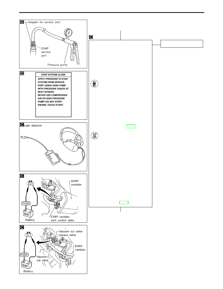
q
A
CHECK FOR EVAP LEAK.
I
Never use compressed air or high
pressure pump.
I
Improper installation of service port
may cause leaking.
I
Do not exceed 4.12 kPa (0.042 kg/cm
2
,
0.6 psi) of pressure in the system.
To locate EVAP leak portion, proceed with
the following steps.
1. Install the EVAP service port adapter
and the pressure pump securely.
2. Turn ignition switch “ON”.
Select “EVAP SYSTEM
CLOSE” of “WORK SUPPORT”
mode with CONSULT-II.
3. Touch “START” and apply
vacuum into the EVAP line until
the pressure indicator reaches
the middle of bar graph.
4. Using EVAP leak detector,
locate the leak portion. For the
leak detector, refer to instruction
manual for more details.
Refer to “Evaporative Emission
Line Drawing”, EC-29.
-------------------------------------------------------------------------------------------------------------------------------------- OR --------------------------------------------------------------------------------------------------------------------------------------
2. Turn ignition switch “OFF”.
3. Apply 12 volts DC to EVAP
canister vent control valve. The
valve will close. (Continue to
apply 12 volts until the end of
test.)
4. Apply 12 volts DC to vacuum
cut valve bypass valve. The
valve will open. (Continue to
apply 12 volts until the end of
test.)
5. Pressurize the EVAP line using
pressure pump with 1.3 to 2.7
kPa (10 to 20 mmHg, 0.39 to
0.79 inHg).
6. Locate the leak using a leak
detector. Refer to the instruction
manual for more details about
the leak detector. Refer to
“Evaporative Emission Line
Drawing”, EC-29.
OK
E
NG
Repair or replace.
q
B
(Go to next page.)
TROUBLE DIAGNOSIS FOR DTC P0455
Evaporative Emission (EVAP) Control System
(Gross Leak) (Cont’d)
H
H
EC-330
SEF765X
SEF597U
SEF396W
SEF394WA
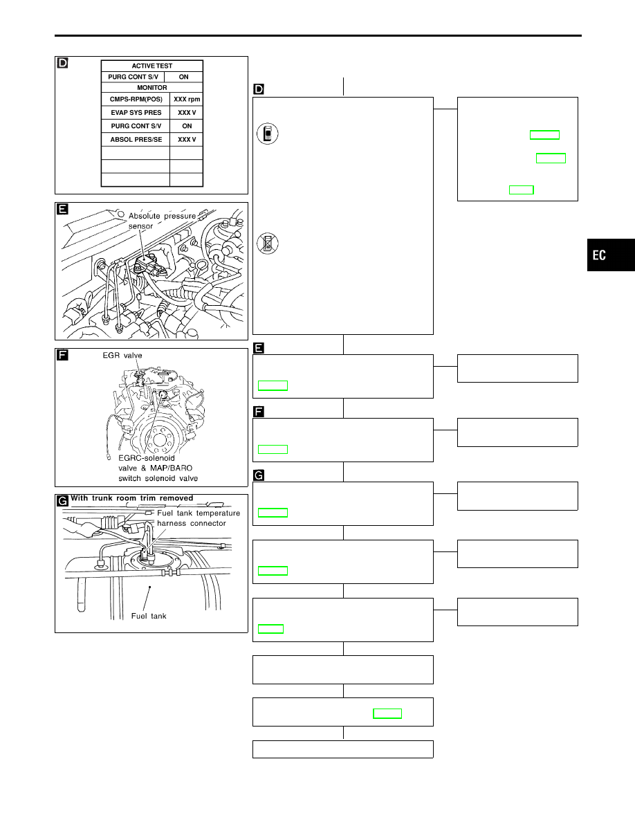
q
B
CHECK COMPONENT
(EVAP canister purge control solenoid
valve).
1. Disconnect vacuum hose to
EVAP canister purge control sole-
noid valve.
2. Start engine.
3. Perform “PURG CONT S/V” in
“ACTIVE TEST” mode.
4. Select “ON” on CONSULT-II
screen to turn on “PURG CONT
S/V”.
5. Check vacuum hose for vacuum
when revving engine up to 2,000
rpm.
Vacuum should exist.
-------------------------------------------------------------------------------------------------------------------------------------- OR --------------------------------------------------------------------------------------------------------------------------------------
1. Start engine and warm it up to
normal operating temperature.
2. Stop engine.
3. Disconnect vacuum hose to
EVAP canister purge control sole-
noid valve.
4. Start engine and let it idle for at
least 60 seconds.
5. Check vacuum hose for vacuum
when revving engine up to 2,000
rpm.
Vacuum should exist.
OK
E
NG
Check the following.
I
EVAP canister purge con-
trol solenoid valve.
Refer to “COMPONENTS
INSPECTION”, EC-332 and
“P1492 EVAP canister
purge control solenoid
valve” for circuit, EC-305.
I
Vacuum hoses for clog-
ging or disconnection.
Refer to “Vacuum Hose
Drawing”, EC-31.
CHECK COMPONENT
(Absolute pressure sensor).
Refer to “COMPONENT INSPECTION”,
OK
E
NG
Replace absolute pressure
sensor.
CHECK COMPONENT
(MAP/BARO switch solenoid valve).
Refer to “COMPONENT INSPECTION”,
OK
E
NG
Replace MAP/BARO switch
solenoid valve.
CHECK COMPONENT
(Fuel tank temperature sensor).
Refer to “COMPONENT INSPECTION”,
OK
E
NG
Replace fuel tank tempera-
ture sensor.
CHECK COMPONENT
(EVAP control system pressure sensor).
Refer to “COMPONENT INSPECTION”,
OK
E
NG
Replace EVAP control sys-
tem pressure sensor.
CHECK COMPONENT
(Refueling control valve).
Refer to “COMPONENT INSPECTION”,
OK
E
NG
Replace refueling control
valve.
Clean EVAP purge line (pipe and rubber
tube) using air blower.
Perform “TROUBLE DIAGNOSIS FOR
INTERMITTENT INCIDENT”, EC-117.
INSPECTION END
GI
MA
EM
LC
FE
AT
PD
FA
RA
BR
ST
RS
BT
HA
EL
IDX
TROUBLE DIAGNOSIS FOR DTC P0455
Evaporative Emission (EVAP) Control System
(Gross Leak) (Cont’d)
H
H
H
H
H
H
H
H
H
EC-331
SEF353Q
SEC049C
SEF763P
SEF593U
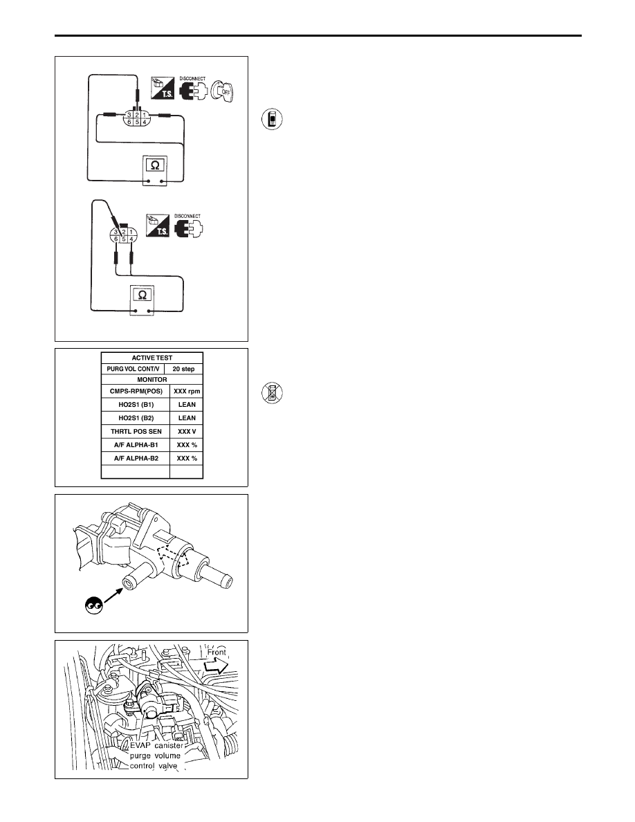
COMPONENT INSPECTION
EVAP canister purge volume control valve
1. Disconnect EVAP canister purge volume control valve
harness connector.
2. Check resistance between the following terminals.
terminal
q
2
and terminals
q
1
,
q
3
terminal
q
5
and terminals
q
4
,
q
6
Resistance:
Approximately 35 - 43
Ω
[At 25°C (77°F)]
3. Reconnect EVAP canister purge volume control valve
harness connector.
4. Remove EVAP canister purge volume control valve
from intake manifold collector and disconnect hoses
from the valve.
(Plug the purge hoses. The EVAP canister purge vol-
ume control valve harness connector should remain
connected.)
5. Turn ignition switch “ON”.
6. Perform “PURG VOL CONT/V” in “ACTIVE TEST”
mode with CONSULT-II. Check that EVAP canister
purge volume control valve shaft moves smoothly for-
ward and backward according to the valve opening.
If NG, replace the EVAP canister purge volume control
valve.
------------------------------------------------------------------------------------------------------------------------------------------------------------------------------------------------------------------------------------------------------ OR ------------------------------------------------------------------------------------------------------------------------------------------------------------------------------------------------------------------------------------------------------
1. Disconnect EVAP canister purge volume control valve
harness connector.
2. Check resistance between the following terminals.
terminal
q
2
and terminals
q
1
,
q
3
terminal
q
5
and terminals
q
4
,
q
6
Resistance:
Approximately 35 - 43
Ω
[At 25°C (77°F)]
3. Reconnect EVAP canister purge volume control valve
harness connector.
4. Remove EVAP canister purge volume control valve
from intake manifold collector and disconnect hoses
from the valve.
(Plug the purge hoses. The EVAP canister purge vol-
ume control valve harness connector should remain
connected.)
5. Turn ignition switch “ON” and “OFF”. Check that EVAP
canister purge volume control valve shaft moves
smoothly forward and backward according to the igni-
tion switch position.
If NG, replace the EVAP canister purge volume control
valve.
TROUBLE DIAGNOSIS FOR DTC P0455
Evaporative Emission (EVAP) Control System
(Gross Leak) (Cont’d)
EC-332
Нет комментариевНе стесняйтесь поделиться с нами вашим ценным мнением.
Текст