Infiniti Q45 (FY33). Manual — part 81
SEF233G
How to Perform Trouble Diagnoses for Quick
and Accurate Repair
INTRODUCTION
SEF234G
The TCS has two electronic control units. One is called the TCS/
ABS control unit. The ABS system has an electronic control unit to
control major functions and for the ABS. The other is the throttle
control module (TAC module) which is used to control the throttle
opening. The control units accept input signals from sensors and
instantly drive actuators. It is essential that both kinds of signals are
proper and stable. Also there should be no such conventional prob-
lems as oil leaks in the TCS operating circuits. Nor should there be
lack of brake fluid or other problems with the brake system.
It is much more difficult to diagnose a problem that occurs intermit-
tently rather than continuously. Most intermittent problems are
caused by poor electric connections or faulty wiring. In this case,
careful checking of suspicious circuits may help prevent the
replacement of good parts.
A visual check only may not find the cause of the problems, so a
road test should be carried out.
Before undertaking actual checks, take just a few minutes to talk
with a customer who approaches with a TCS complaint. The cus-
tomer is a very good source of information on such problems;
especially intermittent ones. Through the talks with the customer,
find out what symptoms are present and under what conditions
they occur.
Start your diagnosis by looking for “conventional” problems first.
This is one of the best ways to troubleshoot brake problems on a
TCS controlled vehicle. Also check related Service Bulletins for
information.
It is strongly recommended that the TCS/ABS control unit be
checked for electrical problems first. Then check the TAC
module.
GI
MA
EM
LC
EC
FE
AT
PD
FA
RA
ST
RS
BT
HA
EL
IDX
TROUBLE DIAGNOSES
BR-41
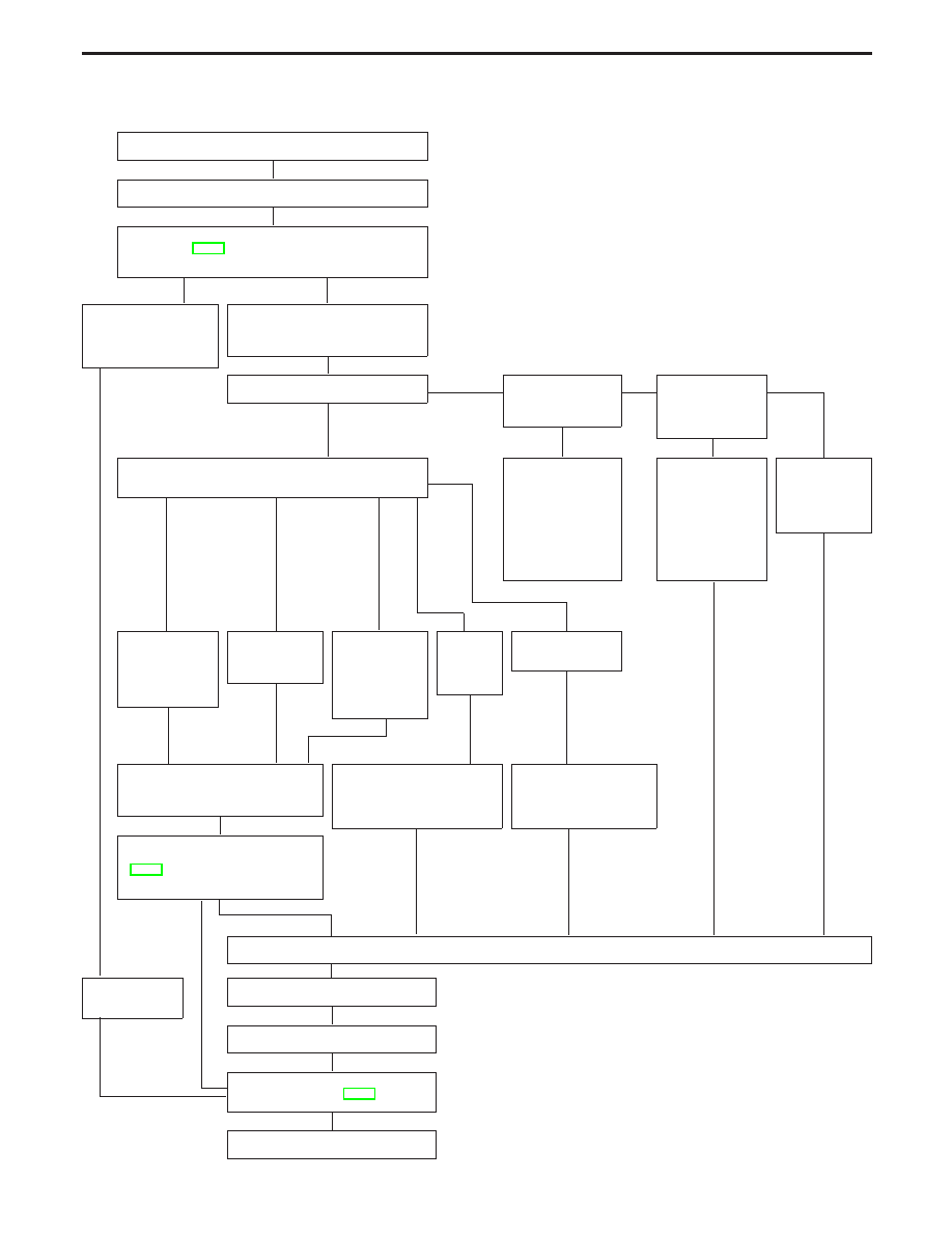
WORK FLOW
Inspection start
Locate trouble area (using diagnostic sheet)
Perform procedures under topic “Basic Inspections 1 and
2”, (Refer to BR-48). Also check related Service bulletins for
information.
Trouble areas corre-
spond with items under
“Basic Inspections 1
and 2”.
H
Trouble areas do not correspond with
items under “Basic Inspections 1 and
2”.
Warning lamp and indicator light.
Yes
E
No
Warning lamp does
not light (ignition
switch “ON”).
Yes
E
No
TCS OFF indicator
does not light
(TCS OFF switch
“ON”).
Yes
H
No
Do ABS warning lamp, TCS OFF indicator and/or TCS OFF
SLIP indicator light?
H
Perform diagnostic
procedure 23, 24,
25 or 26 as outlined
under “TROUBLE
DIAGNOSES FOR
SYMPTOMS”. If
necessary, perform
self-diagnostic pro-
cedures.
Perform diagnostic
procedure 27 as
outlined under
“TROUBLE DIAG-
NOSES FOR
SYMPTOMS”. (If
necessary, per-
form self-diagnos-
tic procedures.)
H
Perform diag-
nostic proce-
dures as per
“Symptom
chart”.
H
H
ABS warning
lamp, TCS OFF
indicator and
SLIP indicator all
light.
TCS OFF indi-
cator and SLIP
indicator light.
H
Warning lamp
and indicators
did not light
when vehicle
was brought in
for inspection.
Only TCS
OFF indi-
cator
lights.
Only SLIP indica-
tor lights.
H
Perform diagnostic procedures using
CONSULT-II or perform self-diagnostic
procedures.
Perform diagnostic procedure
27 as outlined under
“TROUBLE DIAGNOSES FOR
SYMPTOMS”.
H
Perform diagnostic proce-
dure 23 as outlined under
“TROUBLE DIAGNOSES
FOR SYMPTOMS”.
H
Check as per “Entire ABS/TCS trouble
diagnosis flowchart”. (See page
BR-43.) Depending on the diagnostic
result, perform diagnostic procedure.
G
H
E
Check each part.
Repair faulty
parts.
Repair or replace faulty parts.
Erase trouble codes.
NG
Preliminary check (Basic Inspection 3)
Refer to BR-48.
OK
Inspection end
TROUBLE DIAGNOSES
How to Perform Trouble Diagnoses for Quick
and Accurate Repair (Cont’d)
H
H
H
H
H
H
H
H
H
H
H
H
H
H
H
H
H
H
H
BR-42
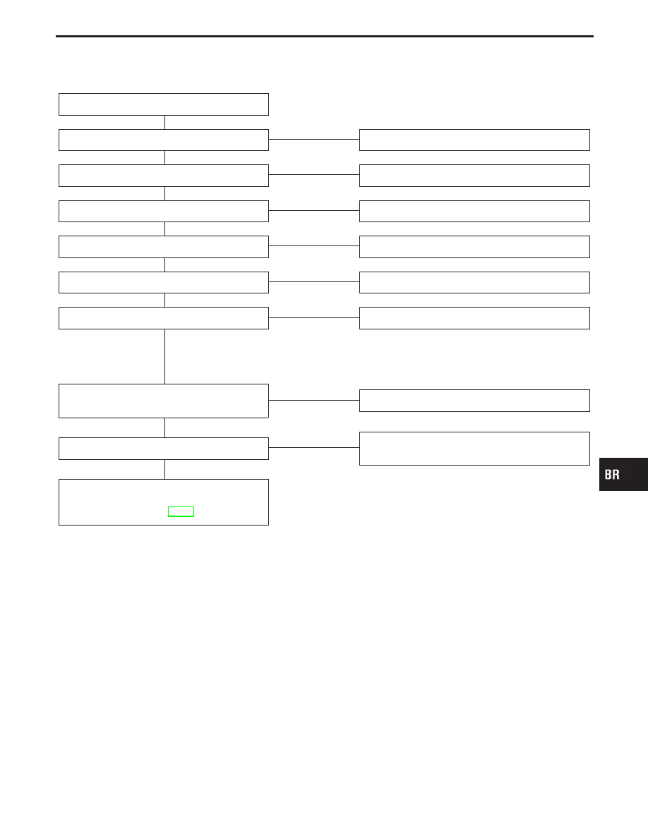
Entire ABS/TCS trouble diagnostic flowchart
Start
Does malfunction code exist?
Yes
E
No
Diagnostic Procedure 26
“TCM COMM” failure
No
E
Yes
Diagnostic Procedure 2
“ENGINE SYSTEM” failure
No
E
Yes
Diagnostic Procedure 1
“ENGINE SPEED SIG” failure
No
E
Yes
Diagnostic Procedure 3
“LAN SIGNAL 2” failure
No
E
Yes
Diagnostic Procedure 5
“LAN SIGNAL 1” failure
No
E
Yes
Diagnostic Procedure 4
NOTE: If “LAN SIGNAL 2” appears on display, do not
check “LAN SIGNAL 1”, “LAN CIRCUIT 1” and/or
“LAN CIRCUIT 2”.
“LAN CIRCUIT 1” failure
“LAN CIRCUIT 2” failure
No
E
Yes
Diagnostic Procedures 5, 6
“LAN SIGNAL 3” failure
No
E
Yes
Faulty ABS/TCS control unit.
Replace.
ABS system failure
(Refer to “SELF-DIAGNOSTIC RESULTS
MODE”, BR-64.)
GI
MA
EM
LC
EC
FE
AT
PD
FA
RA
ST
RS
BT
HA
EL
IDX
TROUBLE DIAGNOSES
How to Perform Trouble Diagnoses for Quick
and Accurate Repair (Cont’d)
H
H
H
H
H
H
H
H
H
BR-43
SBR339B
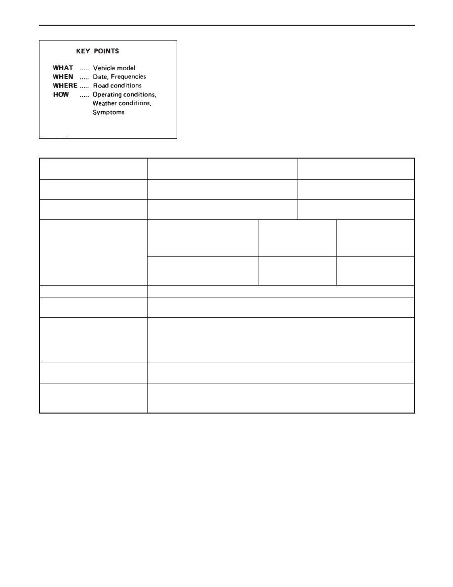
DIAGNOSTIC WORKSHEET
There are many kinds of operating conditions that lead to customer
complaints, even if the system is normal.
A good grasp of such conditions can make troubleshooting faster
and more accurate.
It is important to fully understand the symptoms or under what
conditions a customer complains.
Make good use of a diagnostic worksheet as shown below in order
to utilize all the complaints for troubleshooting.
Worksheet sample
Customer name MR/MS
Model & Year
VIN
Engine #
Trans.
Mileage
Incident Date
Manuf. Date
In Service Date
Symptoms
l
Noise and vibration
(from engine compartment)
l
Noise and vibration
(from axle)
l
Warning/Indicator
activate
l
Firm pedal operation
l
Large stroke pedal
operation
l
TCS does not work
(Rear wheels slip when
accelerating)
l
ABS does not work.
(wheels slip when
braking)
l
Lack of sense of
acceleration
Engine conditions
l
When starting
l
After starting
Road conditions
l
Low friction road (
l
Snow
l
Gravel
l
Other)
l
Bumps/potholes
Driving conditions
l
Full-acceleration
l
High speed cornering
l
Vehicle speed: Greater than 10 km/h (6 MPH)
l
Vehicle speed: 10 km/h (6 MPH) or less
l
Vehicle is stopped
Applying brake conditions
l
Suddenly
l
Gradually
Other conditions
l
Operation of electrical equipment
l
Shift change
l
Other descriptions
TROUBLE DIAGNOSES
How to Perform Trouble Diagnoses for Quick
and Accurate Repair (Cont’d)
BR-44
Нет комментариевНе стесняйтесь поделиться с нами вашим ценным мнением.
Текст