Infiniti Q45 (FY33). Manual — part 80
Removal and Installation
CAUTION:
Be careful not to damage sensor edge and sensor rotor teeth.
When removing the front wheel hub or final drive assemblies,
first remove the ABS wheel sensor from the assembly. Failure
to do so may result in damage to the sensor wires making the
sensor inoperative.
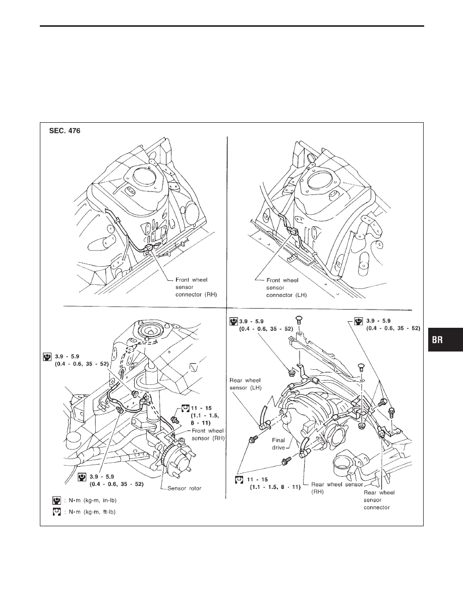
WHEEL SENSORS
SBR622DA
GI
MA
EM
LC
EC
FE
AT
PD
FA
RA
ST
RS
BT
HA
EL
IDX
TRACTION CONTROL SYSTEM — TCS —
BR-37
SBR873CC
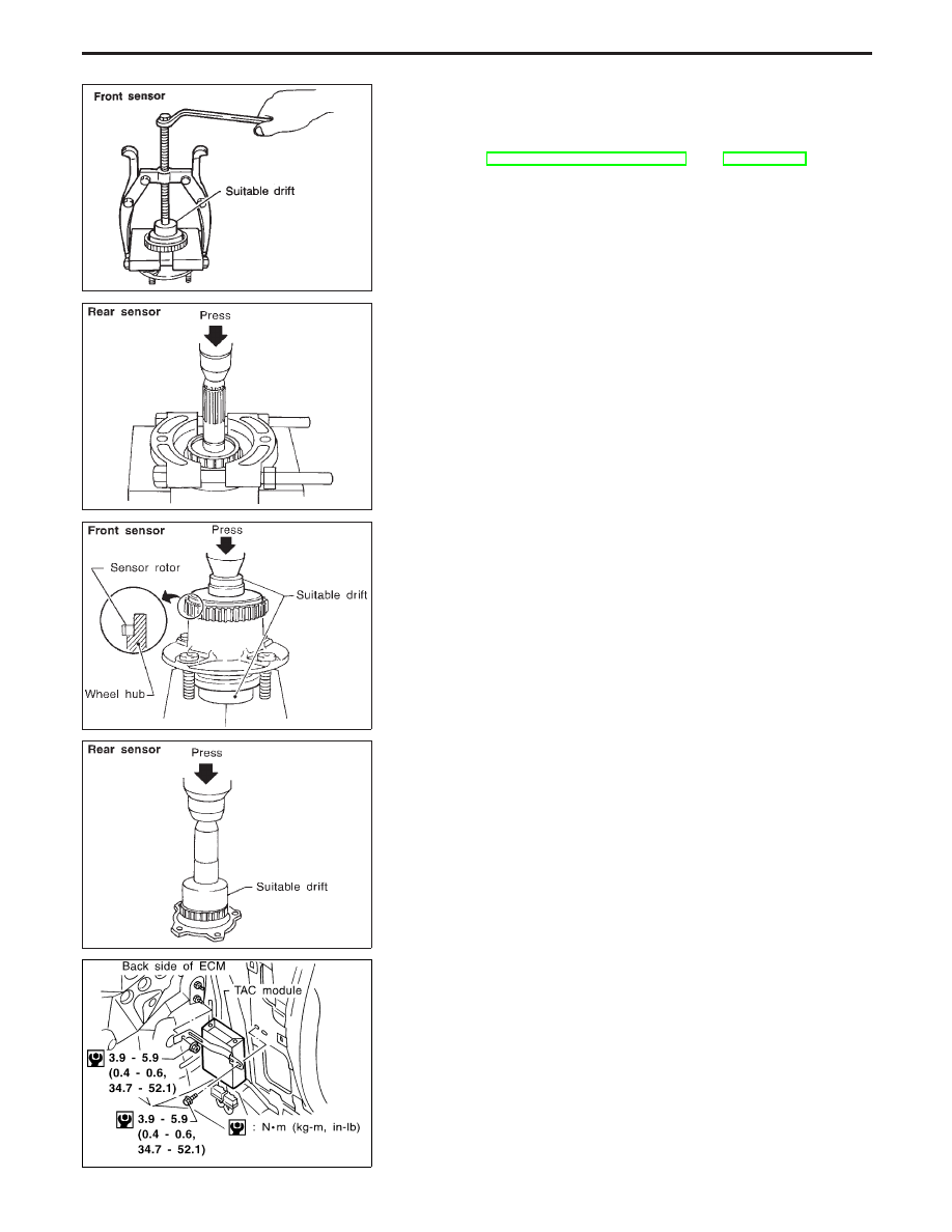
SENSOR ROTOR
Removal
1.
Remove the front wheel hub or final drive companion flange.
Refer to FA section, “FRONT AXLE” and PD section.
2.
Remove the sensor rotor using suitable puller, drift and bear-
ing replacer.
SBR623D
SBR309DA
Installation
Install the sensor rotor using suitable drift and press.
I
Always replace sensor rotor with new one.
I
Pay attention to the direction of front sensor rotor as shown in
figure.
SBR624D
SBR507DD
CONTROL UNIT (TAC module)
CAUTION:
I
When disconnecting or connecting connectors, check ter-
minals to ensure that they are not bent or otherwise dam-
aged.
I
When installing trunk trim clips, be careful not to bend
control unit bracket or bump control unit.
Location: Passenger side, behind dash side lower finisher.
TRACTION CONTROL SYSTEM — TCS —
Removal and Installation (Cont’d)
BR-38
SBR625DA
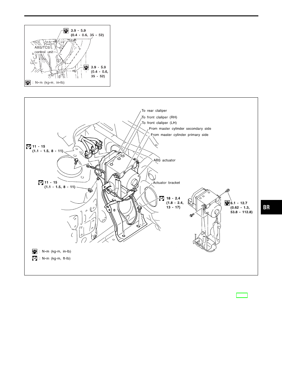
CONTROL UNIT (ABS/TCS control unit)
CAUTION:
I
When disconnecting or connecting connectors, check ter-
minals to ensure that they are not bent or otherwise dam-
aged.
I
When installing trunk trim clips, be careful not to bend
control unit bracket or bump control unit.
Location: Inside instrument panel on passenger’s seat side,
near front pillar
ACTUATOR (ABS relay built-in type)
SBR407E
Removal
1.
Disconnect battery cable.
2.
Drain brake fluid. Refer to “Changing Brake Fluid”, BR-6.
3.
Apply different colored paint to each pipe connector and actua-
tor to prevent incorrect connection.
4.
Disconnect connector, brake pipes and remove fixing nuts and
actuator ground cable.
5.
Remove actuator.
GI
MA
EM
LC
EC
FE
AT
PD
FA
RA
ST
RS
BT
HA
EL
IDX
TRACTION CONTROL SYSTEM — TCS —
Removal and Installation (Cont’d)
BR-39
Installation
CAUTION:
After installing actuator, refill brake fluid. Then bleed air. Refer
to “Bleeding Brake System”, BR-7.
1.
Tighten actuator ground cable.
Place ground cable at a notch of mounting bracket.
2.
Connect brake pipes temporarily.
3.
Tighten fixing nuts.
4.
Tighten brake pipes.
5.
Connect connector and battery cable.
SBR847D
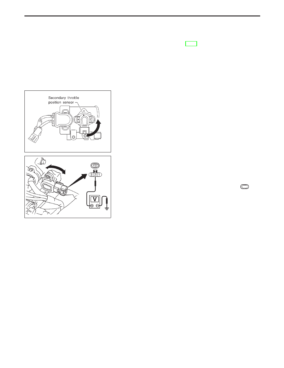
SECONDARY THROTTLE POSITION SENSOR
Removal
1.
Remove collector ornament.
2.
Disconnect harness connector and remove secondary throttle
position sensor.
Installation
I
Insert secondary throttle position sensor into shaft in the direc-
tion shown in the figure, rotate it counterclockwise and tempo-
rarily tighten mounting screws.
SBR848D
Adjustment
1.
After tightening secondary throttle position sensor temporarily,
connect harness connector and warm up the engine.
2.
Turn ignition switch “ON” (engine stopped). Then adjust sen-
sor position so that the sensor output voltage becomes 4.5 -
4.7V (between terminal
q
2
of harness connector
F37
and
ground).
3.
Securely tighten sensor mounting screws.
4.
Check the output voltage of secondary throttle position sensor
again.
TRACTION CONTROL SYSTEM — TCS —
Removal and Installation (Cont’d)
BR-40
Нет комментариевНе стесняйтесь поделиться с нами вашим ценным мнением.
Текст