Infiniti Q45 (FY33). Manual — part 123
Multiport Fuel Injection (MFI) System
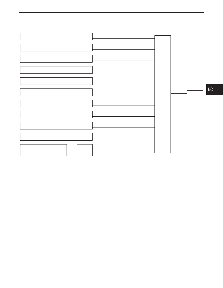
INPUT/OUTPUT SIGNAL LINE
Camshaft position sensor
E
Engine speed and piston position
ECM
E
Injector
Mass air flow sensor
E
Amount of intake air
Engine coolant temperature sensor
E
Engine coolant temperature
Heated oxygen sensor 1 (front)
E
Density of oxygen in exhaust gas
Throttle position sensor
E
Throttle position
Throttle valve idle position
PNP switch (TCM)
E
Park/Neutral position
Vehicle speed sensor
E
Vehicle speed
Ignition switch
E
Start signal
Battery
E
Battery voltage
Heated oxygen sensor 2 (rear)*
E
Density of oxygen in exhaust gas
Secondary throttle position
sensor
E
TAC
module
E
Secondary throttle valve opening angle
*: Under normal conditions, this sensor is not used to control the engine system.
BASIC MULTIPORT FUEL INJECTION
SYSTEM
The amount of fuel injected from the fuel injector is
determined by the ECM. The ECM controls the
length of time the valve remains open (injection
pulse duration). The amount of fuel injected is a
program value in the ECM memory. The program
value is preset by engine operating conditions.
These conditions are determined by input signals
(for engine speed and intake air) from both the cam-
shaft position sensor and the mass air flow sensor.
VARIOUS FUEL INJECTION
INCREASE/DECREASE COMPENSATION
The amount of fuel injected is compensated for to
improve engine performance. This will be made
under various operating conditions as listed below.
<Fuel increase>
I
During warm-up
I
When starting the engine
I
During acceleration
I
Hot-engine operation
I
When selector lever is changed from “N” to “D”
I
High-load, high-speed operation
<Fuel decrease>
I
During deceleration
I
During high speed operation
I
Extremely high engine coolant temperature
I
During TCS operation
I
During high engine speed operation
GI
MA
EM
LC
FE
AT
PD
FA
RA
BR
ST
RS
BT
HA
EL
IDX
ENGINE AND EMISSION BASIC CONTROL SYSTEM DESCRIPTION
EC-21
SEF973Z
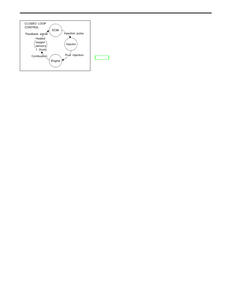
MIXTURE RATIO FEEDBACK CONTROL
The mixture ratio feedback system provides the best air-fuel mix-
ture ratio for driveability and emission control. The three way cata-
lyst can then better reduce CO, HC and NOx emissions. This sys-
tem uses a heated oxygen sensor 1 (front) in the exhaust manifold
to monitor if the engine is rich or lean. The ECM adjusts the injec-
tion pulse width according to the sensor voltage signal. For more
information about heated oxygen sensors 1 (front), refer to pages
EC-166. This maintains the mixture ratio within the range of stoichio-
metric (ideal air-fuel mixture).
This stage is referred to as the closed loop control condition.
Heated oxygen sensors 2 (rear) is located downstream of the three
way catalyst. Even if the switching characteristics of the heated
oxygen sensors 1 (front) shift, the air-fuel ratio is controlled to sto-
ichiometric by the signal from the heated oxygen sensors 2 (rear).
OPEN LOOP CONTROL
The open loop system condition refers to when the ECM detects
any of the following conditions. Feedback control stops in order to
maintain stabilized fuel combustion.
I
Deceleration and acceleration
I
High-load, high-speed operation
I
Malfunction of heated oxygen sensors 1 (front) or its circuit
I
Insufficient activation of heated oxygen sensors 1 (front) at low
engine coolant temperature
I
High-engine coolant temperature
I
During warm-up
I
When starting the engine
MIXTURE RATIO SELF-LEARNING CONTROL
The mixture ratio feedback control system monitors the mixture
ratio signal transmitted from the heated oxygen sensors 1 (front).
This feedback signal is then sent to the ECM. The ECM controls
the basic mixture ratio as close to the theoretical mixture ratio as
possible. However, the basic mixture ratio is not necessarily con-
trolled as originally designed. Both Manufacturing differences (i.e.
mass air flow sensor hot film) and characteristic changes during
operation (i.e. injector clogging) directly affect mixture ratio.
Accordingly, the difference between the basic and theoretical mix-
ture ratios is monitored in this system. This is then computed in
terms of “injection pulse duration” to automatically compensate for
the difference between the two ratios.
“Fuel trim” refers to the feedback compensation value compared
against the basic injection duration. Fuel trim includes short-term
fuel trim and long-term fuel trim.
“Short-term fuel trim” is the short-term fuel compensation used to
maintain the mixture ratio at its theoretical value. The signal from
the heated oxygen sensor 1 (front) indicates whether the mixture
ratio is RICH or LEAN compared to the theoretical value. The sig-
nal then triggers a reduction in fuel volume if the mixture ratio is
rich, and an increase in fuel volume if it is lean.
“Long-term fuel trim” is overall fuel compensation carried out long-
term to compensate for continual deviation of the short-term fuel
trim from the central value. Such deviation will occur due to indi-
vidual engine differences, wear over time and changes in the usage
environment.
ENGINE AND EMISSION BASIC CONTROL SYSTEM DESCRIPTION
Multiport Fuel Injection (MFI) System (Cont’d)
EC-22
MEF404E
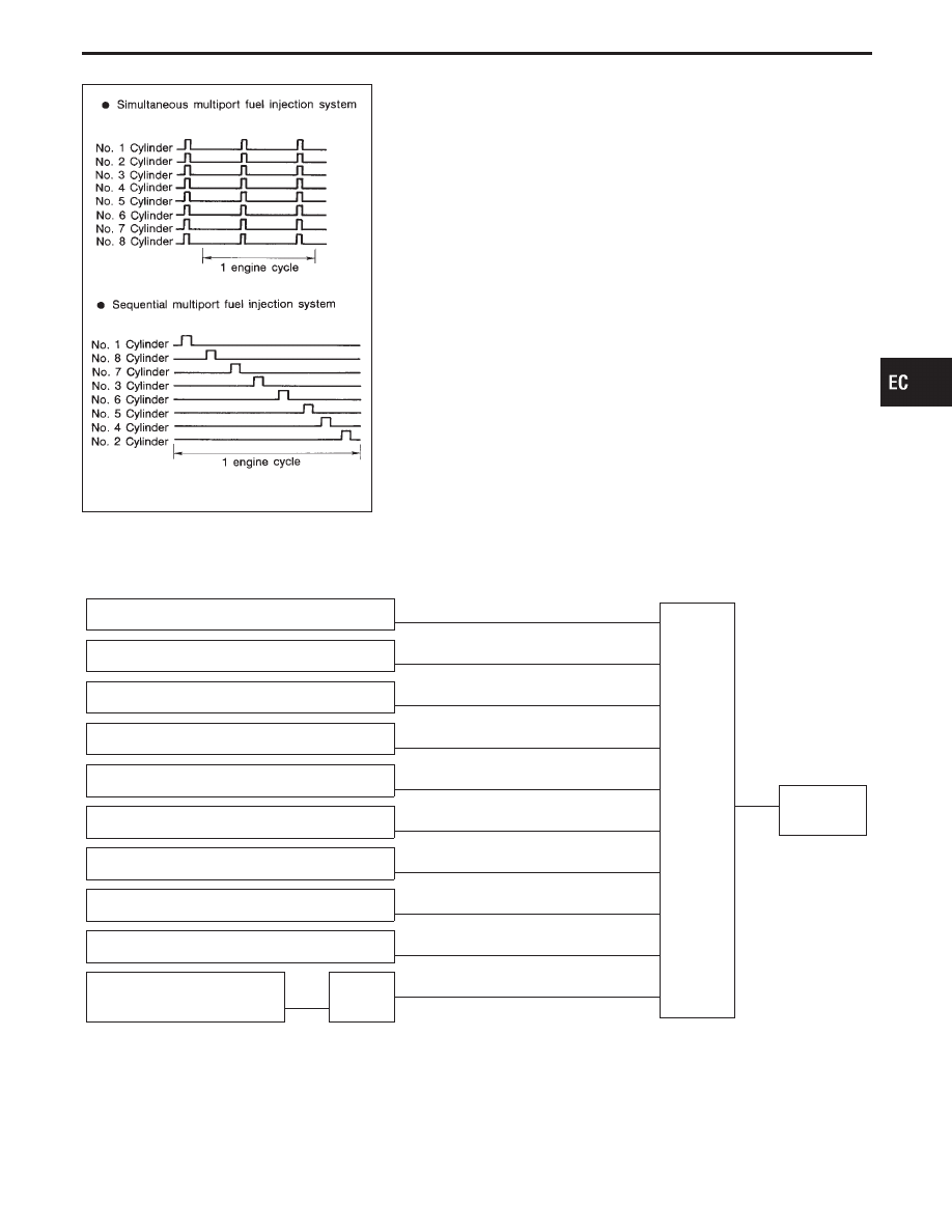
FUEL INJECTION SYSTEM
Two types of systems are used.
Sequential multiport fuel injection system
Fuel is injected into each cylinder during each engine cycle accord-
ing to the firing order. This system is used when the engine is run-
ning.
Simultaneous multiport fuel injection system
Fuel is injected simultaneously into all six cylinders twice each
engine cycle. In other words, pulse signals of the same width are
simultaneously transmitted from the ECM.
The six injectors will then receive the signals two times for each
engine cycle.
This system is used when the engine is being started and/or if the
fail-safe mode (CPU) or crankshaft position sensor (REF) is oper-
ating.
FUEL SHUT-OFF
Fuel to each cylinder is cut off during deceleration or operation of
the engine at excessively high speeds.
Electronic Ignition (EI) System
INPUT/OUTPUT SIGNAL LINE
Camshaft position sensor
E
Engine speed and piston position
ECM
E
Power
transistor
Mass air flow sensor
E
Amount of intake air
Engine coolant temperature sensor
E
Engine coolant temperature
Throttle position sensor
E
Throttle position
Throttle valve idle position
Vehicle speed sensor
E
Vehicle speed
Ignition switch
E
Start signal
Knock sensor
E
Engine knocking
PNP switch (TCM)
E
Park/Neutral position
Battery
E
Battery voltage
Secondary throttle position
sensor
E
TAC
module
E
Throttle position
(Secondary throttle position sensor)
GI
MA
EM
LC
FE
AT
PD
FA
RA
BR
ST
RS
BT
HA
EL
IDX
ENGINE AND EMISSION BASIC CONTROL SYSTEM DESCRIPTION
Multiport Fuel Injection (MFI) System (Cont’d)
EC-23
SEF742M
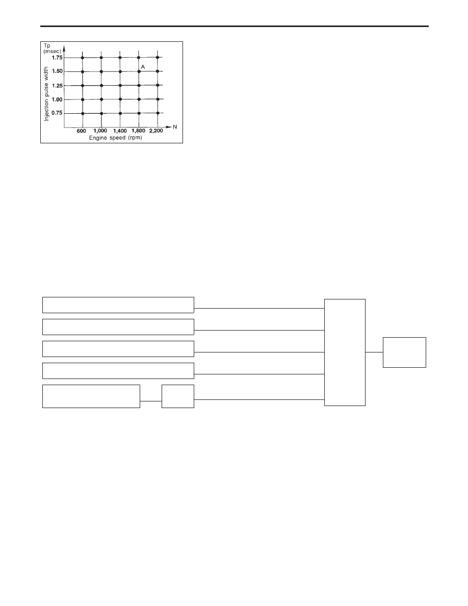
SYSTEM DESCRIPTION
The ignition timing is controlled by the ECM to maintain the best
air-fuel ratio for every running condition of the engine.
The ignition timing data is stored in the ECM. This data forms the
map shown below.
The ECM detects information such as the injection pulse width and
camshaft position sensor signal. Responding to this information,
ignition signals are transmitted to the power transistor.
e.g.
N: 1,800 rpm, Tp: 1.50 msec
A °BTDC
During the following conditions, the ignition timing is revised by the
ECM according to the other data stored in the ECM.
1
At starting
2
During warm-up
3
At idle
4
Hot engine operation
5
At acceleration
The knock sensor retard system is designed only for emergencies.
The basic ignition timing is programmed within the anti-knocking
zone, if recommended fuel is used under dry conditions. The retard
system does not operate under normal driving conditions.
If engine knocking occurs, the knock sensor monitors the condition.
The signal is transmitted to the ECM. The ECM retards the ignition
timing to eliminate the knocking condition.
Air Conditioning Cut Control
INPUT/OUTPUT SIGNAL LINE
Air conditioner switch
E
Air conditioner “ON” signal
ECM
E
Air condi-
tioner
relay
Throttle position sensor
E
Throttle valve opening angle
Camshaft position sensor
E
Engine speed
Ignition switch
E
Start signal
Secondary throttle position
sensor
E
TAC
module
E
Secondary throttle valve opening angle
SYSTEM DESCRIPTION
This system improves engine operation when the air
conditioner is used.
Under the following conditions, the air conditioner is
turned off.
I
When the accelerator pedal is fully depressed.
I
When cranking the engine.
I
At high engine speeds.
I
After a few seconds when the TCS has started
operating.
ENGINE AND EMISSION BASIC CONTROL SYSTEM DESCRIPTION
Electronic Ignition (EI) System (Cont’d)
EC-24
Нет комментариевНе стесняйтесь поделиться с нами вашим ценным мнением.
Текст