Infiniti Q45 (FY33). Manual — part 122
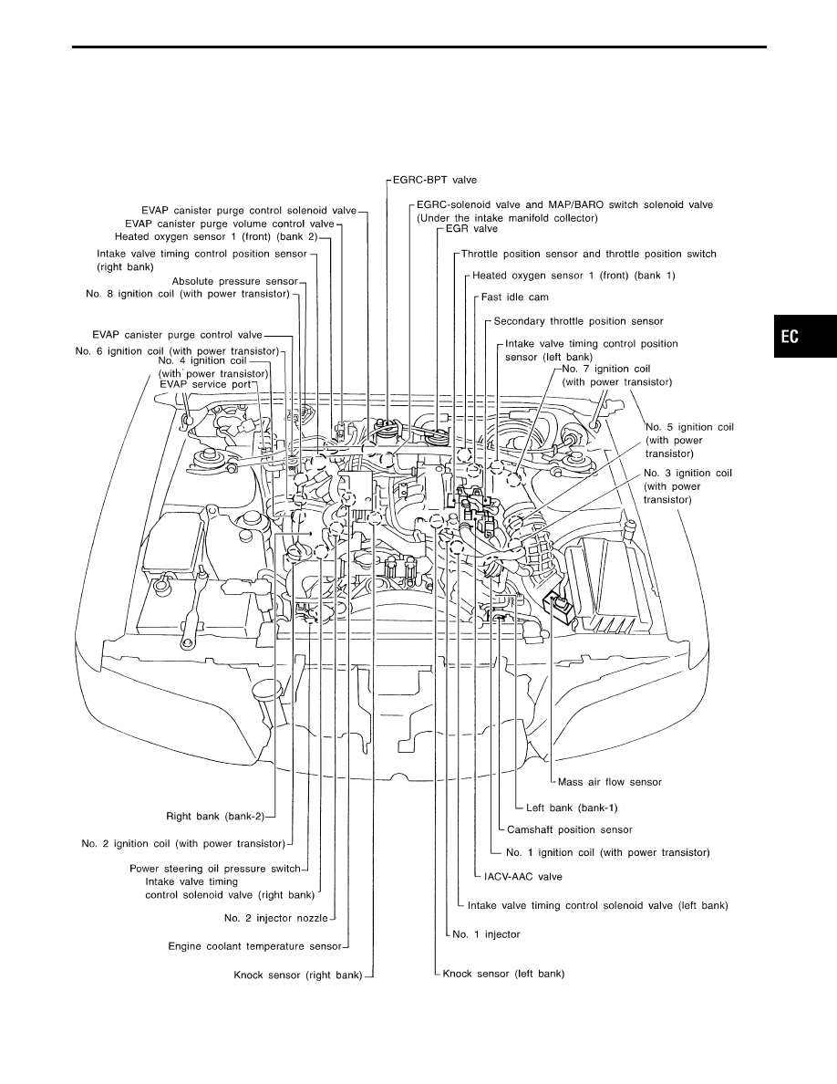
Engine Control Component Parts Location
SEF347WA
GI
MA
EM
LC
FE
AT
PD
FA
RA
BR
ST
RS
BT
HA
EL
IDX
ENGINE AND EMISSION CONTROL OVERALL SYSTEM
EC-17
SEF348WA
SEF554T
SEF392WA
SEF386X
SEF037T
SEF038TA
SEF039TA
SEF349W
ENGINE AND EMISSION CONTROL OVERALL SYSTEM
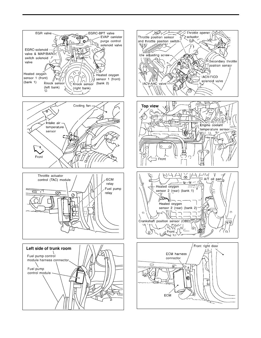
Engine Control Component Parts Location
(Cont’d)
EC-18
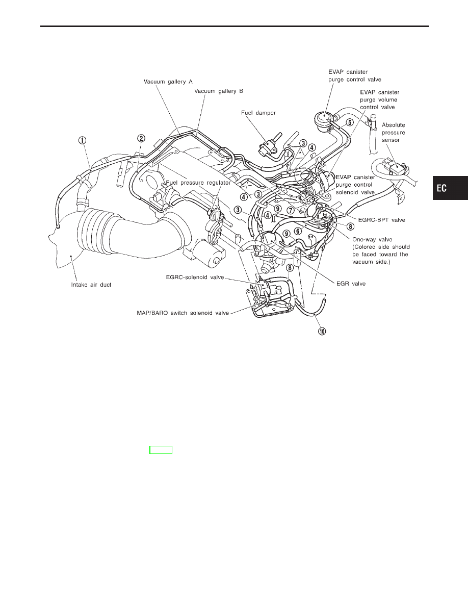
Vacuum Hose Drawing
SEF208U
q
1
Intake air duct to vacuum gallery A
q
2
Fuel pressure regulator to vacuum gallery B
q
3
Vacuum gallery A to EGRC-solenoid valve, MAP/BARO
switch solenoid valve and EVAP canister purge control
solenoid valve
q
4
Intake manifold collector to EGRC-solenoid valve
q
5
EVAP canister purge control valve to EVAP canister purge
control solenoid valve
q
6
Intake manifold collector to One-way valve
q
7
One-way valve to EVAP canister purge control solenoid
valve
q
8
EGRC-BPT valve to EGRC-solenoid valve
q
9
Intake manifold collector to MAP/BARO switch solenoid
valve
q
10
Absolute pressure sensor to MAP/BARO switch solenoid
valve
Refer to “System Diagram”, EC-16, for vacuum control system.
Note: Do not use soapy water or any type of solvent while installing vacuum hoses or purge hoses.
GI
MA
EM
LC
FE
AT
PD
FA
RA
BR
ST
RS
BT
HA
EL
IDX
ENGINE AND EMISSION CONTROL OVERALL SYSTEM
EC-19
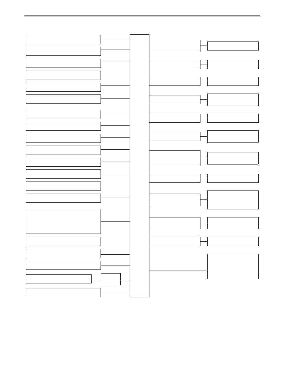
System Chart
Camshaft position sensor
E
ECM
Mass air flow sensor
E
Engine coolant temperature sensor
E
Heated oxygen sensors 1 (front)
E
Ignition switch
E
Throttle position sensor
E
*4
Closed throttle position switch
E
Park/Neutral position (PNP) switch (TCM)
E
Vehicle speed sensor
E
Air conditioner switch
E
Knock sensor
E
Battery voltage
E
Electrical load
E
Intake air temperature sensor
E
*1
I
EGR temperature sensor
I
Crankshaft position sensor (OBD)
I
Intake valve timing control position sensor
I
Absolute pressure sensor
I
EVAP control system pressure sensor
I
Fuel tank temperature sensor
E
Heated oxygen sensors 2 (rear)*3
E
TCM (Transmission Control Module)*2
E
Power steering oil pressure switch
E
Secondary throttle position sensor
E
TAC
module
E
TCS signal
E
*1: These sensors are not used to control the engine system. They are used only for the on board diagnosis.
*2: The DTC related to A/T and gear position will be sent to ECM.
*3: This sensor is not used to control the engine system under normal conditions.
*4: This switch will operate in place of the throttle position sensor to control EVAP parts if the sensor malfunctions.
Fuel injection &
mixture ratio control
E
Injectors
Electronic ignition system
E
Power transistor
Idle air control system
E
IACV-AAC valve
Intake valve timing control
E
Intake valve timing control
solenoid valve
EGR control
E
EGRC-solenoid valve
Fuel pump control
E
Fuel pump relay and
Fuel pump control module
Heated oxygen sensor 1 (front)
monitor & on board diagnostic
system
E
Malfunction indicator lamp
(On the instrument panel)
Acceleration cut control
E
Air conditioner relay
EVAP canister purge flow con-
trol
E
I
EVAP canister purge volume
control valve
I
EVAP canister purge control
solenoid valve
Heated oxygen sensors 1 & 2
heaters (front and rear) control
E
Heated oxygen sensors 1 & 2
heaters (front and rear)
Cooling fan control
E
Cooling fan relay
E
I
EVAP canister vent control
valve
I
Vacuum cut valve bypass
valve
I
MAP/BARO switch solenoid
valve
ENGINE AND EMISSION CONTROL OVERALL SYSTEM
EC-20
Нет комментариевНе стесняйтесь поделиться с нами вашим ценным мнением.
Текст