Infiniti Q45 (FY33). Manual — part 41
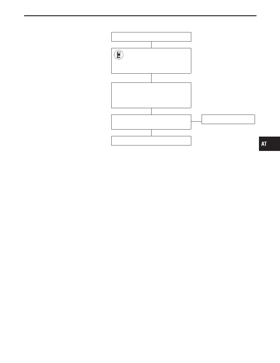
DIAGNOSTIC PROCEDURE
INSPECTION START
1) Turn ignition switch “ON” and
select “SELF DIAG RESULTS”
mode for A/T with CONSULT-II.
2) Touch “ERASE”.
PERFORM DIAGNOSTIC TROUBLE
CODE (DTC) CONFIRMATION PROCE-
DURE.
See previous page.
Is the “CONTROL UNIT (RAM) or CON-
TROL UNIT (ROM)” displayed again?
No
E
Yes
Replace TCM.
INSPECTION END
GI
MA
EM
LC
EC
FE
PD
FA
RA
BR
ST
RS
BT
HA
EL
IDX
CONTROL UNIT (RAM), CONTROL UNIT (ROM)
TCM (Transmission Control Module) (Cont’d)
H
H
H
H
AT-161
SAT909I
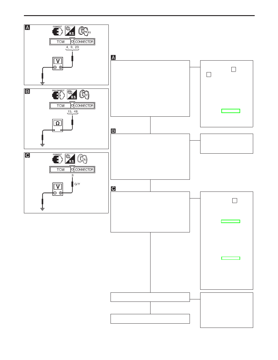
1. O/D OFF Indicator Lamp Does Not Come On
SYMPTOM:
O/D OFF indicator lamp does not come on for about 2 seconds
when turning ignition switch to “ON”.
SAT910I
SAT103J
CHECK TCM POWER SOURCE.
1. Turn ignition switch to “ON” position.
(Do not start engine.)
2. Check voltage between TCM terminals
q
4
,
q
9
,
q
23
and ground.
Voltage: Battery voltage
3. Turn ignition switch to “OFF” position.
4. Check voltage between TCM terminal
q
23
and ground.
Voltage: Battery voltage
OK
E
NG
Check the following items:
I
10A fuse [No.
18
and
28
, located in the fuse
block (J/B)]
I
Harness for short or
open between ignition
switch and TCM (Main
harness)
I
Ignition switch
Refer to EL section
(“POWER SUPPLY
ROUTING”).
CHECK TCM GROUND CIRCUIT.
1. Turn ignition switch to “OFF” position.
2. Disconnect TCM harness connector.
3. Check continuity between TCM termi-
nals
q
15
,
q
48
and ground.
Continuity should exist.
If OK, check harness for short to
ground and short to power.
OK
E
NG
Repair open circuit or short
to ground or short to power
in harness or connectors.
CHECK LAMP CIRCUIT.
1. Turn ignition switch to “ON” position.
2. Set overdrive control switch to “ON”
position.
3. Check voltage between TCM terminal
q
3
and ground.
Voltage: Battery voltage
OK
E
NG
Check the following items:
I
7.5A fuse [No.
4
,
located in the fuse block
(J/B)]
I
O/D OFF indicator lamp
Refer to EL section
(“WARNING LAMPS”).
I
Harness for short or
open between ignition
switch and O/D OFF
indicator lamp (Main har-
ness)
Refer to EL section
(“POWER SUPPLY
ROUTING”).
I
Harness for short or
open between O/D OFF
indicator lamp and TCM
Check again.
OK
E
NG
1. Perform TCM input/
output signal inspection.
2. If NG, recheck TCM pin
terminals for damage or
loose connection with
harness connector.
INSPECTION END
TROUBLE DIAGNOSES FOR SYMPTOMS
H
H
H
H
H
AT-162
SAT367J
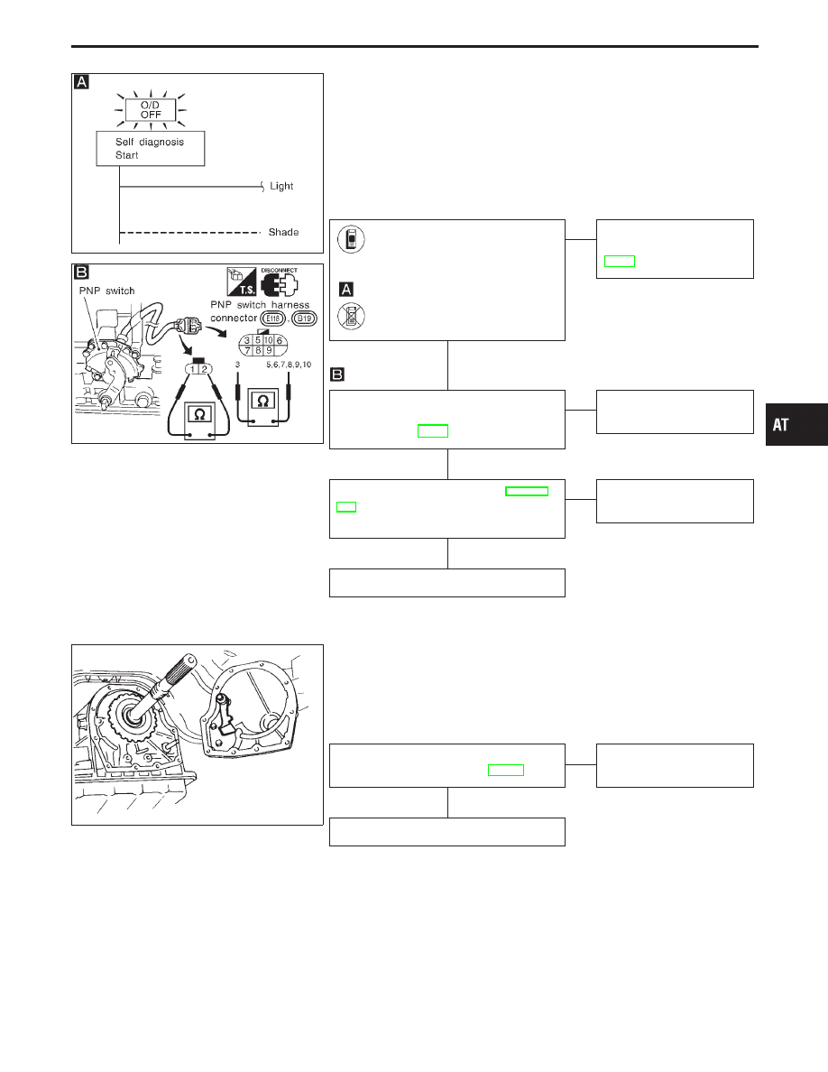
2. Engine Cannot Be Started In “P” and “N”
Position
SYMPTOM:
I
Engine cannot be started with selector lever in “P” or “N”
position.
I
Engine can be started with selector lever in “D”, “2”, “1”
or “R” position.
SAT051JA
Does “TCM INPUT SIGNALS” in
“DATA MONITOR” show damage
to PNP switch circuit?
-------------------------------------------------------------------------------------------------------------------------------------- OR --------------------------------------------------------------------------------------------------------------------------------------
Does self-diagnosis show damage
to PNP switch circuit?
No
E
Yes
Check PNP switch circuit.
Refer to “DTC P0705”,
AT-81.
Check for short or open of PNP switch
2-pin connector. Refer to “COMPONENT
INSPECTION”, AT-84.
OK
E
NG
Repair or replace PNP
switch.
Check starting system. Refer to EL sec-
tion (“System Description”, “STARTING
SYSTEM”).
OK
E
NG
Repair or replace damaged
parts.
INSPECTION END
SAT133B
3. In “P” Position, Vehicle Moves Forward Or
Backward When Pushed
SYMPTOM:
Vehicle moves when it is pushed forward or backward with
selector lever in “P” position.
Check parking components. Refer to
“Parking Pawl Components”, AT-256.
OK
E
NG
Repair or replace damaged
parts.
INSPECTION END
GI
MA
EM
LC
EC
FE
PD
FA
RA
BR
ST
RS
BT
HA
EL
IDX
TROUBLE DIAGNOSES FOR SYMPTOMS
H
H
H
H
AT-163
SAT367J
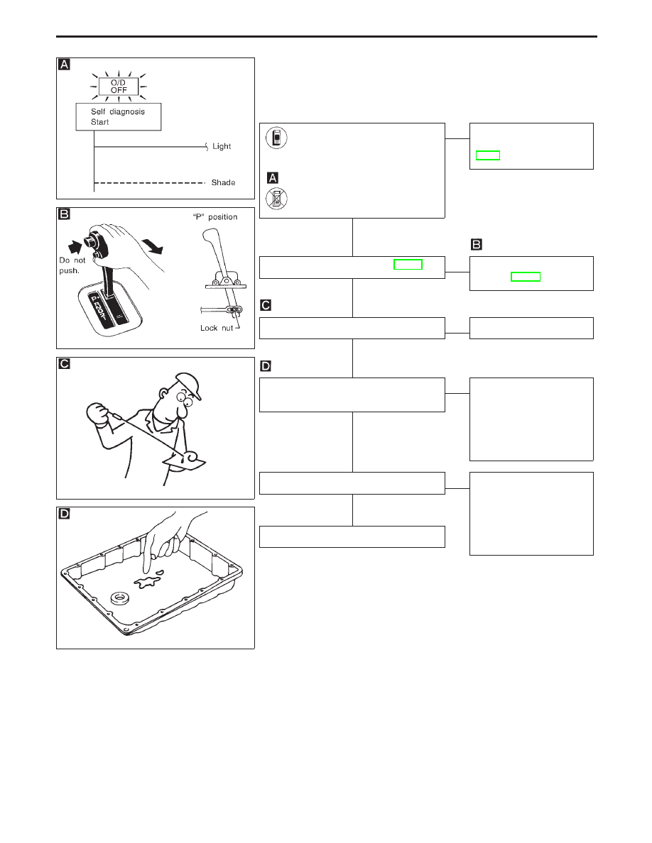
4. In “N” Position, Vehicle Moves
SYMPTOM:
Vehicle moves forward or backward when selecting “N” posi-
tion.
SAT578I
SAT638A
SAT171B
Does “TCM INPUT SIGNALS” in
“DATA MONITOR” show damage
to PNP switch circuit?
-------------------------------------------------------------------------------------------------------------------------------------- OR --------------------------------------------------------------------------------------------------------------------------------------
Does self-diagnosis show damage
to PNP switch circuit?
No
E
Yes
Check PNP switch circuit.
Refer to “DTC P0705”,
AT-81.
Check control linkage. Refer to AT-197.
OK
E
NG
Adjust control linkage.
Refer to AT-197.
Check A/T fluid level again.
OK
E
NG
Refill ATF.
1. Remove oil pan.
2. Check A/T fluid condition.
OK
E
NG
1. Disassemble A/T.
2. Check the following
items:
I
Forward clutch assembly
I
Overrun clutch assembly
I
Reverse clutch assembly
Check again.
OK
E
NG
1. Perform TCM input/
output signal inspection.
2. If NG, recheck TCM pin
terminals for damage or
loose connection with
harness connector.
INSPECTION END
TROUBLE DIAGNOSES FOR SYMPTOMS
H
H
H
H
H
H
AT-164
Нет комментариевНе стесняйтесь поделиться с нами вашим ценным мнением.
Текст