Infiniti Q45 (FY33). Manual — part 432
Removal and Installation
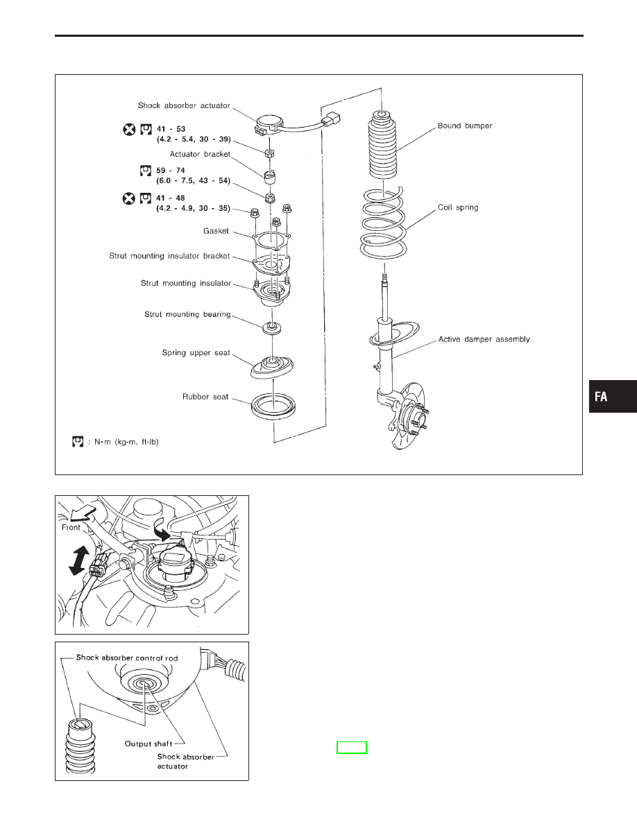
SFA927B
SFA928B
I
Disconnect sub-harness connector.
I
Turn shock absorber actuator counterclockwise, then remove
from bracket.
SFA671A
I
Before installing actuator, ensure shock absorber control
rod is aligned with actuator output shaft.
Otherwise, actuator may be damaged.
I
Refer to FRONT SUSPENSION for other procedures.
INSPECTION
I
Replace shock absorber assembly if it is damaged.
Refer to FRONT SUSPENSION — Coil Spring and Strut
Assembly (FA-17).
GI
MA
EM
LC
EC
FE
AT
PD
RA
BR
ST
RS
BT
HA
EL
IDX
ACTIVE DAMPER SUSPENSION
FA-27
How to Perform Trouble Diagnoses for Quick
and Accurate Repair
INTRODUCTION
I
Before troubleshooting, verify customer complaints concerning
his vehicle.
I
If a vehicle problem is hard to reproduce, harnesses, harness
connectors and/or terminals may often be faulty. Hold and
shake these parts by hand to make sure they are securely
connected.
I
When using a circuit tester to measure voltage or resistance
of each circuit, be careful not to expand connector terminals
unnecessarily.
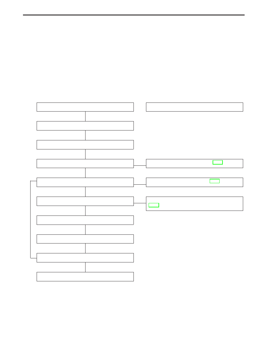
WORK FLOW
INSPECTION START
Reference item
Verify customer complaints.
Determine related reference item concerning symptom.
Preliminary inspection
F
Preliminary check (Refer to FA-31.)
E
Perform self-diagnosis.
F
Self-diagnosis (Refer to FA-39.)
Check symptom.
F
TROUBLE DIAGNOSES FOR SYMPTOMS (Refer to
FA-51.)
Repair or replace faulty parts.
Perform self-diagnosis.
Prior to final checks, turn ignition switch to “OFF”
,
“ON” fol-
lowing the self-diagnosis to initialize actuator positioning.
NG
Final check
OK
END
TROUBLE DIAGNOSES
H
H
H
H
H
H
H
H
H
FA-28
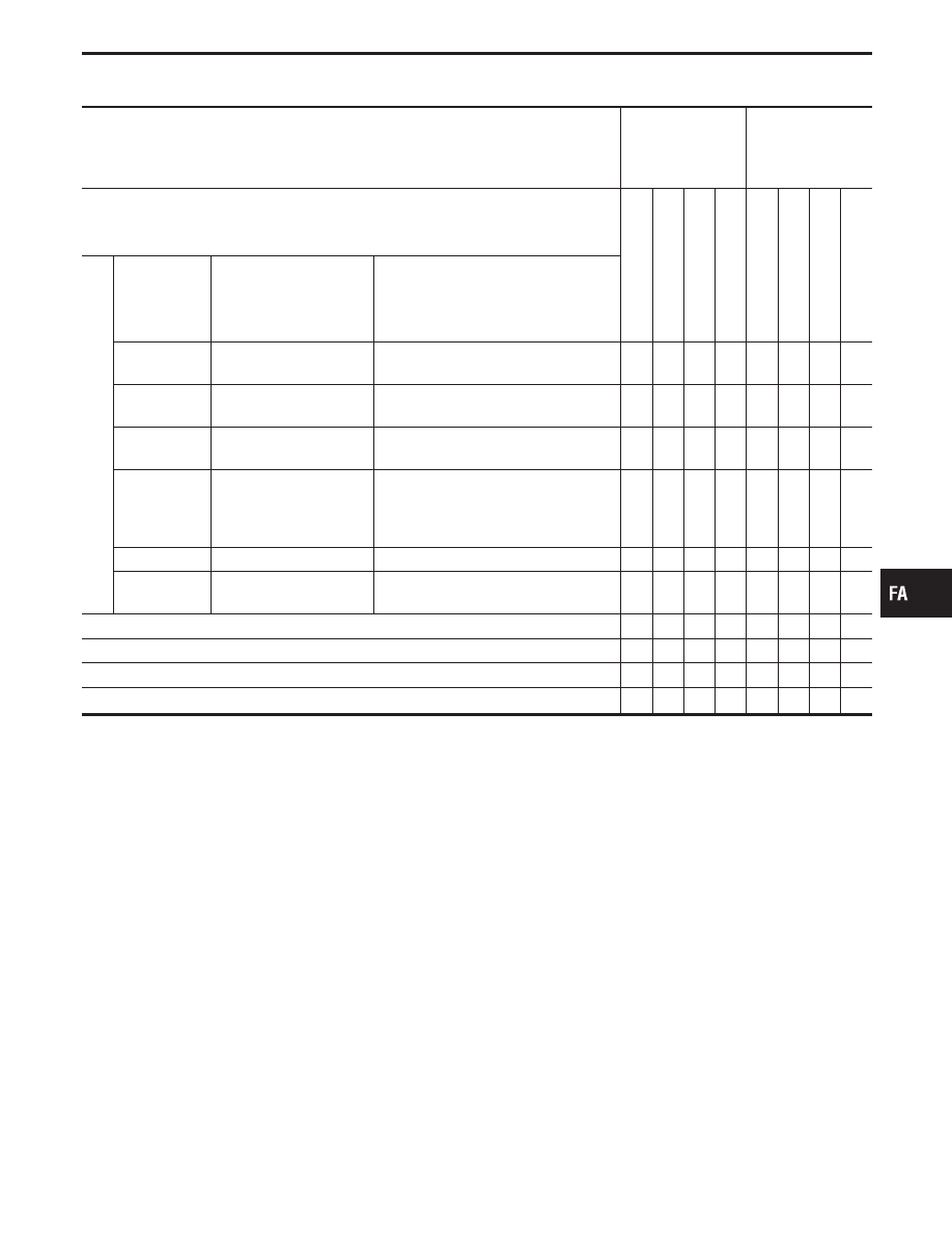
Symptom Chart
PROCEDURE
TROUBLE DIAG-
NOSES FOR
SELF-DIAGNOS-
TIC ITEMS
TROUBLE DIAG-
NOSES FOR
SYMPTOMS
SYMPTOM
Diagnostic
Procedure
1
Diagnostic
Procedure
2
Diagnostic
Procedure
3
Diagnostic
Procedure
4
Diagnostic
Procedure
5
Diagnostic
Procedure
6
Diagnostic
Procedure
7
Diagnostic
Procedure
8
Self-diagnostic
results
Self-diagnosis
code No.
Diagnosed part
CONSULT-II indication
11
Vehicle speed sensor
VHCL SPEED SE
[km/h] or [mph]
q
12
Steering angle sensor
(Steering angle signal)
STEERING ANG [°]
q
13
Steering angle sensor
(Steering neutral signal)
NEUTRAL SIG
[ON-OFF]
q
14
Stop lamp switch
DATA MONITOR mode “STOP LAMP
SW”
Brake pedal depressed: ON
Brake pedal release: OFF
q
22
Vertical G sensor front
VERTI G SE FL [G]
q
23
Vertical G sensor rear
right side
VERTI G SE RR [G]
q
Indicator lamp in meter cluster does not illuminate.
q
Hard or soft (riding comfort) feel.
q
Heavy steering operation during stationary turns.
q
Light steering during high-speed operation.
q
GI
MA
EM
LC
EC
FE
AT
PD
RA
BR
ST
RS
BT
HA
EL
IDX
TROUBLE DIAGNOSES
FA-29
Fail-safe Remarks
FAIL-SAFE FUNCTION (Active damper suspension)
The active damper suspension electronically controls the shock
absorber dampening force. If, for some reason, the dampening
force falls under any of the conditions listed in the “Fail-safe items”
table below, the fail-safe system will activate to maintain a constant
level of shock absorber dampening force. If symptoms (such as
unstable steering, unpleasant riding comfort, etc.) are pointed out,
check and correct the faulty part or area using the diagnostic pro-
cedure outlined under “Diagnostic Procedure 6 (Hard or soft feel)”.
Refer to FA-53.
SFA662B
FAIL-SAFE FUNCTION (Electric control power steering)
The electric control power steering (EPS) electrically controls the
solenoid valve in response to vehicle speeds. If any of the condi-
tions listed in the table below are encountered, the fail-safe system
will activate so that a constant level of steering force is maintained
during high-speed operation. If abnormal steering force is
indicated, check and correct the problem using the diagnostic pro-
cedure outlined under “Diagnostic Procedure 7 (Heavy steering
operation during stationary turns)”. Refer to FA-56.
Fail-safe items
Item
Fail-safe input conditions
Fail-safe cancel condi-
tions
Operation during fail-safe
Vehicle speed sensor
I
Vehicle speed signal cannot be entered for more
than 10 seconds when the vehicle is running
with the engine revolution greater than 1,500
rpm.
I
Vehicle speed signal changes from a value of
greater than 30 km/h (19 MPH) to a value of
less than 2 km/h (1 MPH) within 1.4 seconds.
A signal corresponding to
a vehicle speed of
greater than 2 km/h (1
MPH) is entered.
I
Shock absorber damp-
ening force is main-
tained at a preset
value.
I
Power steering control
current is maintained
at approximately
0.18A.
Steering angle sensor
A steering signal of greater than 1° does not
change for more than 180 seconds when vehicle
speed is greater than 60 km/h (37 MPH).
A steering signal of
greater than 1° is
entered.
Shock absorber dampen-
ing force is maintained at
a preset value.
Steering angle (neutral)
signal
I
Steering neutral signal is not entered (“ON”) at
all while vehicle is being driven a distance of
more than 10 km (6 miles).
I
Steering neutral signal is not entered (“ON”) at
all when steering wheel is turned at least 360° in
either direction.
I
Steering neutral signal is entered (“ON”) only
while steering wheel is being turned at least 50°
in either direction.
More than one ON-OFF
signal are entered.
Shock absorber dampen-
ing force is maintained at
a preset value.
Vertical G sensor
I
Vertical G sensor signal corresponding to a volt-
age of greater than 4.5 volts does not change
for 2 seconds.
I
Vertical G sensor signal corresponding to a volt-
age of less than 0.5 volts does not change for 2
seconds.
Vertical G sensor signal
corresponding to a volt-
age of greater than 1 volt
or less than 4 volts.
When any of the vertical
G sensors are deter-
mined to be faulty, shock
absorber dampening
force is maintained at a
preset value.
Stop lamp switch
Fail-safe system does not process data.
Faulty area is displayed when self-diagnosis is performed.
NOTE: Even after the fail-safe function is canceled, the fail-safe processed history is retained in the control unit memory.
TROUBLE DIAGNOSES
FA-30
Нет комментариевНе стесняйтесь поделиться с нами вашим ценным мнением.
Текст