Infiniti Q45 (FY33). Manual — part 213
Tandem Throttle Position Sensor
This diagnosis is for tandem throttles (main throttle and secondary
throttle). The quantity of intake air is determined by these two
throttle valves. A rationality check is then carried out by ECM after
monitoring the signals of these two throttle position sensors.
ON BOARD DIAGNOSIS LOGIC
Diagnostic Trouble
Code No.
Malfunction is detected when ...
Check Items
(Possible Cause)
P1125
1502
I
Rationally incorrect voltage is entered to ECM com-
pared with the signals from mass air flow sensor,
camshaft position sensor and IACV-AAC valve.
I
Harness or connectors
(The sensor circuits are open or shorted.)
I
Throttle position sensor or secondary throttle posi-
tion sensor
I
Throttle actuator control (TAC) module
DIAGNOSTIC TROUBLE CODE CONFIRMATION
PROCEDURE
NOTE:
If “DIAGNOSTIC TROUBLE CODE CONFIRMATION PROCE-
DURE” has been previously conducted, always turn ignition
switch “OFF” and wait at least 5 seconds before conducting
the next test.
1) Start engine and warm it up to normal operating tem-
perature.
2) Stop engine and wait at least 5 seconds.
3) Turn ignition switch “ON”.
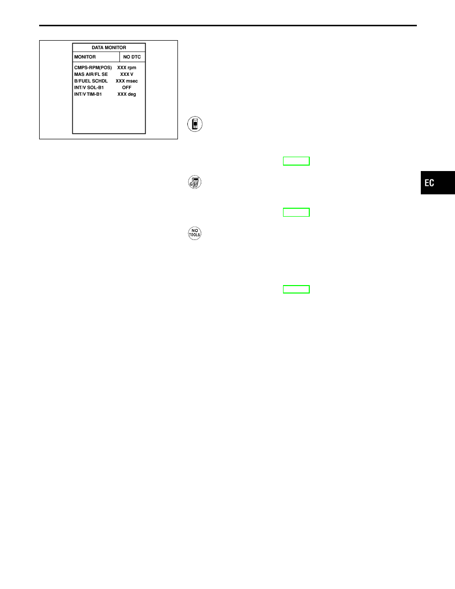
4) Select “DATA MONITOR” mode with CONSULT-II.
5) Start engine and run it for 15 seconds.
------------------------------------------------------------------------------------------------------------------------------------------------------------------------------------------------------------------------------------------------------ OR ------------------------------------------------------------------------------------------------------------------------------------------------------------------------------------------------------------------------------------------------------
1) Start engine and warm it up to normal operating tem-
perature.
2) Stop engine and wait at least 5 seconds.
3) Start engine and run it for 15 seconds.
4) Select “MODE 7” with GST.
------------------------------------------------------------------------------------------------------------------------------------------------------------------------------------------------------------------------------------------------------ OR ------------------------------------------------------------------------------------------------------------------------------------------------------------------------------------------------------------------------------------------------------
1) Start engine and warm it up to normal operating tem-
perature.
2) Stop engine and wait at least 5 seconds.
3) Start engine and run it for 15 seconds.
4) Turn ignition switch “OFF”, wait at least 5 seconds and
then turn “ON”.
5) Perform “Diagnostic Test Mode II (Self-diagnostic
results)” with ECM.
DIAGNOSTIC PROCEDURE
Refer to TROUBLE DIAGNOSIS FOR DTC P0120, EC-150 OR
Refer to TROUBLE DIAGNOSIS FOR DTC P1120, EC-375.
GI
MA
EM
LC
FE
AT
PD
FA
RA
BR
ST
RS
BT
HA
EL
IDX
TROUBLE DIAGNOSIS FOR DTC P1125
EC-381
SEF599T
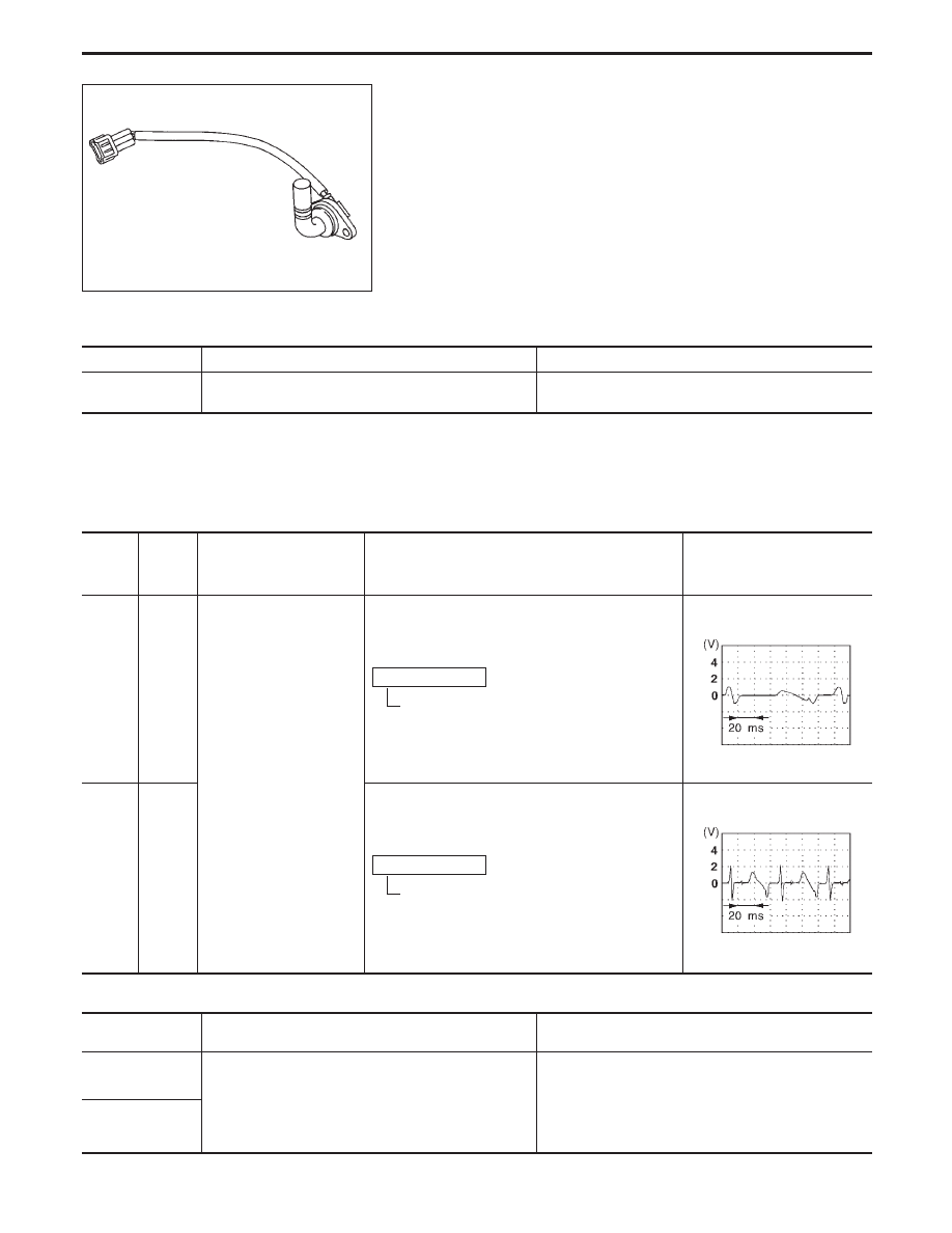
Intake Valve Timing Control Position Sensor
(P1140: Left bank), (P1145: Right bank)
COMPONENT DESCRIPTION
The intake valve timing control position sensor is located rearmost
of the left-bank cylinder head. This sensor detects a signal (intake
valve position) generated by the cutout portion of camshaft and
sends it to the ECM. This sensor is not used to control the engine
system. It is used only for the on board diagnosis of intake valve
timing control.
CONSULT-II REFERENCE VALUE IN DATA MONITOR MODE
Specification data are reference values.
MONITOR ITEM
CONDITION
SPECIFICATION
INT/V TIM-B1
INT/V TIM-B2
I
Engine is running.
Advanced angle (degree) of the intake camshaft should be
displayed.
ECM TERMINALS AND REFERENCE VALUE
Specification data are reference values, and are measured between each terminal and ground.
CAUTION:
Do not use ECM ground terminals when measuring voltage. Doing so may result in damage to the
ECM’s transistor. Use a ground other than ECM terminals such as the body ground.
TER-
MINAL
NO.
WIRE
COLOR
ITEM
CONDITION
DATA
(DC voltage)
70
(RH)
R/L
Intake valve timing con-
trol position sensors
Engine is running.
Idle speed
Approximately 0V
SEF551T
71
(LH)
L/W
Engine is running.
Engine speed is 2,000 rpm.
Approximately 0V
SEF552T
ON BOARD DIAGNOSIS LOGIC
Diagnostic Trouble
Code No.
Malfunction is detected when .
Check Items
(Possible Cause)
P1140
1303
(Left bank)
The proper pulse signal from the intake valve timing
control position sensors is not sent to ECM while the
engine is running at the specified engine speed.
I
Harness or connectors
(The left bank intake valve timing control position
sensor circuit is open.)
I
Intake valve timing control position sensor
I
Accumulation of debris to the signal pick-up portion
of the camshaft
P1145
1304
(Right bank)
TROUBLE DIAGNOSIS FOR DTC P1140 (B1), P1145 (B2)
EC-382
SEF276Y
DIAGNOSTIC TROUBLE CODE CONFIRMATION
PROCEDURE
NOTE:
If “DIAGNOSTIC TROUBLE CODE CONFIRMATION PROCE-
DURE” has been previously conducted, always turn ignition
switch “OFF” and wait at least 5 seconds before conducting
the next test.
1) Turn ignition switch “ON” and select “DATA MONITOR”
mode with CONSULT-II.
2) Start engine and keep the engine speed at 2,000 rpm
and wait at least 15 seconds.
3) If 1st trip DTC is detected, go to “DIAGNOSTIC
PROCEDURE”, EC-386.
------------------------------------------------------------------------------------------------------------------------------------------------------------------------------------------------------------------------------------------------------ OR ------------------------------------------------------------------------------------------------------------------------------------------------------------------------------------------------------------------------------------------------------
1) Start engine and keep the engine speed at 2,000 rpm
and wait at least 15 seconds.
2) Select “MODE 7” with GST.
3) If 1st trip DTC is detected, go to “DIAGNOSTIC
PROCEDURE”, EC-386.
------------------------------------------------------------------------------------------------------------------------------------------------------------------------------------------------------------------------------------------------------ OR ------------------------------------------------------------------------------------------------------------------------------------------------------------------------------------------------------------------------------------------------------
1) Start engine and keep the engine speed at 2,000 rpm
and wait at least 15 seconds.
2) Turn ignition switch “OFF”, wait at least 5 seconds and
then turn “ON”.
3) Perform “Diagnostic Test Mode II (Self-diagnostic
results)” with ECM.
4) If 1st trip DTC is detected, go to “DIAGNOSTIC
PROCEDURE”, EC-386.
GI
MA
EM
LC
FE
AT
PD
FA
RA
BR
ST
RS
BT
HA
EL
IDX
TROUBLE DIAGNOSIS FOR DTC P1140 (B1), P1145 (B2)
Intake Valve Timing Control Position Sensor
(P1140: Left bank), (P1145: Right bank) (Cont’d)
EC-383
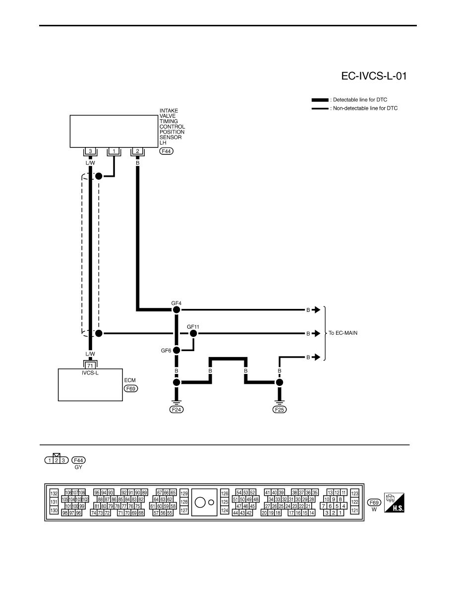
LEFT BANK
TEC757
TROUBLE DIAGNOSIS FOR DTC P1140 (B1), P1145 (B2)
Intake Valve Timing Control Position Sensor
(P1140: Left bank), (P1145: Right bank) (Cont’d)
EC-384
Нет комментариевНе стесняйтесь поделиться с нами вашим ценным мнением.
Текст