Infiniti Q45 (FY33). Manual — part 212
SEF065T
SEF580R
SEF749W
Procedure for malfunction B.
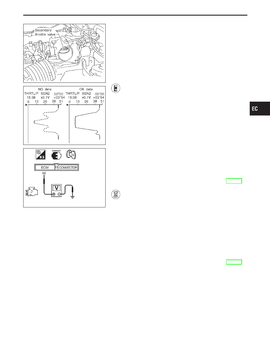
OVERALL FUNCTION CHECK
Use this procedure to check the overall function of the secondary
throttle position sensor circuit. During this check, a DTC might not
be confirmed.
WARNING:
Before touching the secondary throttle valve, be sure to dis-
connect the throttle motor harness connector. Failure to do so
may cause injury due to accidental actuation of the valve.
1) Start engine and warm it up to normal operating tem-
perature.
2) Turn ignition switch “OFF” and disconnect throttle motor
harness connector.
3) Remove intake air duct.
4) Turn ignition switch “ON”.
5) Select “MANUAL TRIG” and “HI SPEED” in “DATA
MONITOR” mode with CONSULT-II.
6) Select “THRTL/P SEN2” in “DATA MONITOR” mode
with CONSULT-II.
7) Press RECORD on CONSULT-II SCREEN at the same
time close the secondary throttle valve by hand.
8) Print out the recorded data and check the following:
I
The voltage when secondary throttle valve is closed
by hand is approximately 0.60 - 1.15V.
I
The voltage decrease is linear in response to second-
ary throttle valve closing.
I
The voltage when secondary throttle valve is fully
opened is approximately 4.3 - 4.7V.
9) If NG, go to “DIAGNOSTIC PROCEDURE”, EC-379.
------------------------------------------------------------------------------------------------------------------------------------------------------------------------------------------------------------------------------------------------------ OR ------------------------------------------------------------------------------------------------------------------------------------------------------------------------------------------------------------------------------------------------------
1) Start engine and warm it up to normal operating tem-
perature.
2) Turn ignition switch “OFF” and disconnect throttle motor
harness connector.
3) Remove intake air duct.
4) Turn ignition switch “ON”.
5) Check the voltage between ECM terminal
q
66
and
ground, then check the following:
I
The voltage when secondary throttle valve is closed
by hand is approximately 0.4 - 0.86V.
I
The voltage decrease is linear in response to second-
ary throttle valve closing.
I
The voltage when secondary throttle valve is fully
opened is approximately 3.3 - 3.5V.
6) If NG, go to “DIAGNOSTIC PROCEDURE”, EC-379.
GI
MA
EM
LC
FE
AT
PD
FA
RA
BR
ST
RS
BT
HA
EL
IDX
TROUBLE DIAGNOSIS FOR DTC P1120
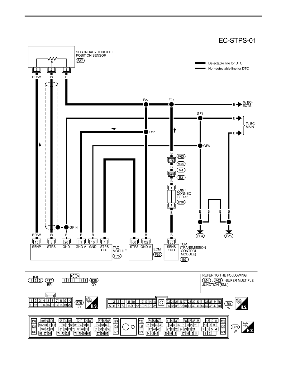
Secondary Throttle Position Sensor (STPS)
(Cont’d)
EC-377
TEC066M
TROUBLE DIAGNOSIS FOR DTC P1120
Secondary Throttle Position Sensor (STPS)
(Cont’d)
EC-378
SEF066T
SEF899Q
SEF377U
SEF900Q
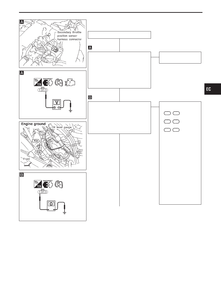
DIAGNOSTIC PROCEDURE
INSPECTION START
CHECK POWER SUPPLY.
1. Turn ignition switch “OFF”.
2. Disconnect secondary throttle position
sensor harness connector.
3. Turn ignition switch “ON”.
4. Check voltage between terminal
q
3
and
ground with CONSULT-II or tester.
Voltage: Approximately 5V
OK
E
NG
Repair harness or connec-
tors.
CHECK GROUND CIRCUIT.
1. Turn ignition switch “OFF”.
2. Loosen and retighten ground screw.
3. Check harness continuity between ter-
minal
q
1
and engine ground.
Continuity should exist.
If OK, check harness for short to power.
OK
E
NG
Check the following.
I
Harness connectors
F63
,
M49
I
Harness connectors
M4
,
B3
I
Harness connectors
F62
,
F61
I
Joint connector-16
I
Harness for open or
short between sensor
and throttle actuator con-
trol (TAC) module
I
Harness for open or
short between secondary
throttle position sensor
and ECM
I
Harness for open or
short between secondary
throttle position sensor
and TCM (Transmission
Control Module)
If NG, repair open circuit or
short to power in harness
or connectors.
q
A
(Go to next page.)
GI
MA
EM
LC
FE
AT
PD
FA
RA
BR
ST
RS
BT
HA
EL
IDX
TROUBLE DIAGNOSIS FOR DTC P1120
Secondary Throttle Position Sensor (STPS)
(Cont’d)
H
H
H
EC-379
SEF447U
SEF340R
q
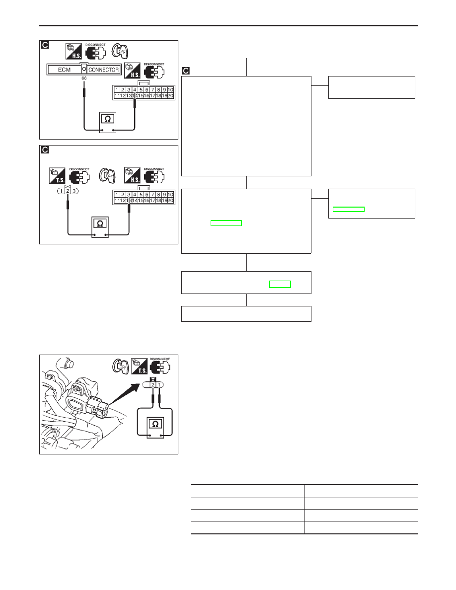
A
CHECK INPUT SIGNAL CIRCUIT.
1. Disconnect ECM harness connector
and throttle actuator control module
harness connector.
2. Check harness continuity between ECM
terminal
q
66
and throttle actuator control
module terminal
q
4
, sensor terminal
q
2
and throttle actuator control module ter-
minal
q
3
.
Continuity should exist.
If NG, repair open circuit or short to
ground or short to power in harness or
connectors.
OK
E
NG
Repair harness or connec-
tors.
CHECK COMPONENT
(Secondary throttle position sensor).
Refer to “COMPONENT INSPECTION”
below.
Refer to BR section (“Adjustment for Sec-
ondary Throttle Position”, “TRACTION
CONTROL SYSTEM — TCS —”) for
adjustment.
OK
E
NG
Replace secondary throttle
position sensor. Refer to
BR section.
Perform “TROUBLE DIAGNOSIS FOR
INTERMITTENT INCIDENT”, EC-117.
INSPECTION END
SEF787T
COMPONENT INSPECTION
Secondary throttle position sensor
WARNING:
Before touching the secondary throttle valve, be sure to dis-
connect the throttle motor harness connector. Failure to do so
may cause injury due to accidental actuation of the valve.
1.
Turn ignition switch “OFF”.
2.
Disconnect secondary throttle position sensor harness con-
nector.
3.
Disconnect throttle motor harness connector.
4.
Remove intake air duct.
5.
Make sure that resistance between terminals
q
2
and
q
1
changes when opening secondary throttle valve manually.
Throttle valve conditions
Resistance at 25°C (77°F)
Completely closed
Approximately 0.6 k
Ω
Partially open
0.6 - 4.0 k
Ω
Completely open
Approximately 5 k
Ω
TROUBLE DIAGNOSIS FOR DTC P1120
Secondary Throttle Position Sensor (STPS)
(Cont’d)
H
H
H
H
EC-380
Нет комментариевНе стесняйтесь поделиться с нами вашим ценным мнением.
Текст